Using Particle Systems
Despite their sophistication, particle systems are easy to set up and simple to use. This section describes how to use premade particle systems from the Particle Emitters category of the Library. Afterward, this section explains how to create a simple particle system of your own.
Using the Particle Library
The easiest way to add a particle system to your project is to use a preset in the Particle Emitters category of the Library. There are many types of particle effects to choose from. If you find one close to what you need, you can easily customize its parameters after you add it to your project. Particle systems are added to a project exactly like any other object.
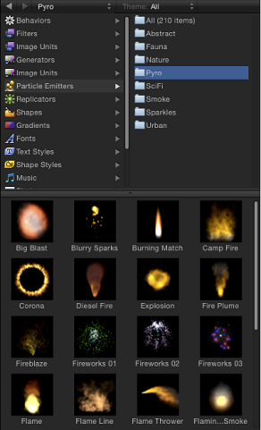
In the Library, click the Particle Emitters category.
Click a particle subcategory, such as Nature, Pyro, SciFi, and so on.
Select a particle preset in the Library stack.
An animated preview of the selected particle emitter plays in the preview area.
Note: If the preview does not start playing, click the Play button in the preview area. To automatically play items selected in the File Browser or Library, choose Motion > Preferences (or press Command-Comma), then select “Play items automatically on a single click” in the File Browser & Library section of the General pane.
When you find a particle preset you want to use, do one of the following:
Click Apply to add the selected particle system to your project at the center of the Canvas.
Note: If Create Layers At is set to “Start of project” in the Project pane of Motion Preferences, the particle system is added at the first frame.
Drag the particle system from the Library stack into the Canvas to the position where you want it to appear.
Drag the particle system from the Library stack into a group in the Layers list or Timeline. The particle system appears at the center of the Canvas.
Drag the particle system from the Library stack to the track area of the Timeline. When you reach the frame where you want the new particles to start, release the mouse button.
The new particle system layer appears in your project, composited against any other layers you’ve already added.
When you add a particle system from the Library, the system acts as it did in the preview area. If necessary, you can edit a particle system’s Emitter parameters in the HUD to tailor them to your own use.
Note: You can only modify a particle system after it is added to a project.
The HUD displays a selected particle system’s most essential parameters, including the size and number of particles created, how long they remain onscreen, how fast they move, and the direction and area in which they travel. Select an individual cell in the Layers list or Timeline to edit its parameters in the HUD.
For more detailed information on using the particle HUD, see Customizing a Particle System Emitter. For more comprehensive information on customizing all of a particle system’s parameters, see Emitter and Cell Parameters.
Creating a Simple Custom Particle System
Although Motion provides a wide variety of particle system presets, many times you’ll want to create something completely new. Creating a particle system begins with selecting a layer in your project to use as the source for a cell in a new particle emitter.
You can use any layer in your project as a source for a cell in an emitter, including still graphics, animation or video clips, or shapes created in Motion. The layer you select when you create an emitter becomes the first cell in that particle system. In the Layers list, cells appear as a sublayer under the emitter layer. The cell specifies the look of the actual particles generated in the Canvas.
Note: You can also use a group as the source for an emitter cell, but your computer’s processing performance may slow drastically.
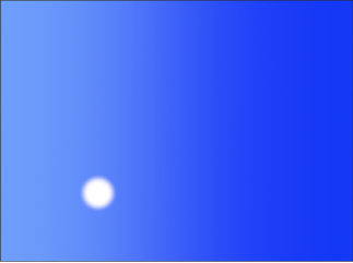
Create a layer to serve as the cell source for the particles that your emitter will generate.
This example uses an image of a simple white circular gradient, such as the “basic blur” image located in the Library (in the Particle Images subcategory of the Content category).

Move the object in the Canvas to the location where you want the center of your particle system to be.
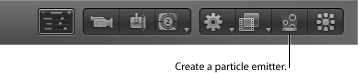
Select the object, then do one of the following:
In the toolbar, click the Make Particles button.
Press E.
After you add an emitter to the project, the following occurs:
An emitter appears in the Layers list and is selected.
A cell containing the image to be “particle-ized” appears underneath the emitter.
The original source layer (the cell source) is disabled.
Note: Changes made to the original source layer, such as opacity or shearing, are also applied to the particles even after the emitter is created.
In the Canvas, the emitter bounding box appears.
The first particle appears in the Canvas in the same location as the original layer. Although it appears as if the particle is selected, the bounding box represents the entire emitter.
The Emitter HUD appears. If you have hidden the HUD, press F7.
Note: For projects with a frame rate greater than 30 frames per second (fps), at times only the bounding box (not the first particle) might appear at the first frame of your project. Because Motion generates particles at a default rate of 30 per second, there is no guarantee that a particle will appear on every frame.
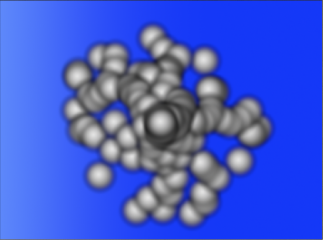
By default, the first frame of a new particle system (with a single cell) has one particle. If you play your project (press Space bar), additional particles are generated and emerge from the center of the emitter.
By default, new cells emit one particle per frame in all directions (for 30-fps projects), and each particle moves 100 pixels per second away from the emitter over a lifetime of 5 seconds (150 frames in a 30-fps project).

Note: The Initial Number parameter in the Particle Cell Inspector allows you to change the default behavior so a particle system begins with a burst of particles at the first frame. For more information, see Emitter and Cell Parameters.
Using Multiple Cells in a Single Emitter
When you create a particle system from scratch, you don’t have to restrict yourself to using just one cell. You can create a particle system that emits many kinds of overlapping particles by placing multiple cells inside of a single emitter in the Layers list.
You can add as many cells as you want in a single emitter. Each cell has its own particle cell parameters that govern how particles from that cell are created. When selected in the Layers list, each cell displays its own Particle Cell Inspector. Particle systems with multiple cells generate particles from each cell simultaneously, according to each cell’s parameters.
For an example of using multiple cells in a single emitter, see Example 2: Creating Animated Pixie Dust.
Additional cells can be created by selecting multiple layers when initially creating the emitter, or by dragging additional source layers onto the emitter in the Layers list.
Note: When multiple sources are used to create a particle system, the resulting emitter is positioned at the average of the sources’ positions.
Customizing a Particle System Emitter
When you create an emitter, the particle system starts working according to the default parameters in its Emitter and Particle Cell Inspectors. You can use the Emitter HUD to easily change the most important of these parameters to suit your needs.
Select the emitter.
The HUD appears when you select the emitter. If the HUD does not appear, press F7.
Using the HUD to Create a Simple Smoke Effect
In this example, use the Emitter HUD to create a smoke effect. Use the emitter created in Creating a Simple Custom Particle System.
Before making adjustments to the selected particle system, it can be helpful to drag the playhead forward in the Timeline to a frame where you can see the particle system in full effect. That way, any adjustments you make are readily apparent.
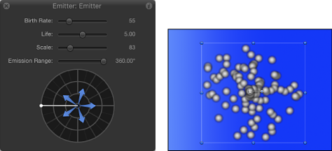
In this example , the size of each particle is so big, it’s hard to make out any texture in the particle system.
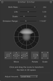
In the Emitter HUD, drag the Scale slider to the left to reduce every particle’s size so the individual particles are more identifiable.
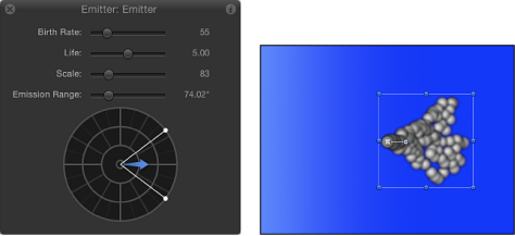
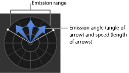
In the Emitter HUD, click anywhere along the outer ring of the emission control (the circle with blue arrows) and drag rightward to define a narrow segment that limits the range of the angle at which particles are created (the emission range).
As you drag, both points defining the emission range rotate around the center of the emission control symmetrically. When the emission range forms the rightward angle shown below, release the mouse button. (As you adjust the emission range, the particles rearrange themselves in the Canvas, enabling you to see the resulting effect.)
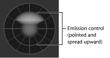
To make the particles drift upward, drag in the middle of the Emission Range segment, rotating the blue arrow counterclockwise until it points up and slightly to the right of the center control; continue dragging outward to lengthen the arrow.
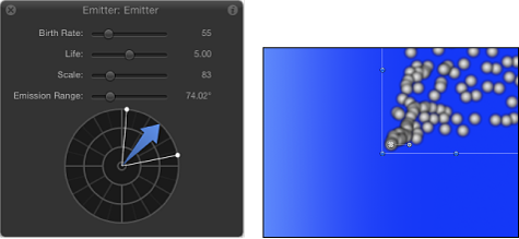
The emission angle of the particles updates in the Canvas to reflect the new setting in the HUD.
Remember: Although the angle of the arrow controls the emission angle of the particles, the length of the arrow controls the speed of the particles. The longer the arrow, the faster the particles, and vice versa.
At this point, the particles are all moving in the correct direction, but there aren’t very many of them (there isn’t much of a fire yet).
In the Emitter HUD, drag the Birth Rate slider to the right to increase the number of particles created by the emitter.
As you increase the birth rate, more particles are created, forming a nearly unified column of “smoke.” The particles move farther apart as they drift away from the emitter.
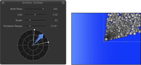
As you can see, a single object can be used to create a credible column of smoke rising gently into the sky.
Although the HUD controls are quite powerful, the Emitter and Particle Cell panes in the Inspector have many more parameters you can customize. For more information, see Emitter and Cell Parameters.
Emitter HUD Parameters
The HUD contains the most frequently used emitter controls necessary to modify a particle system’s size and shape. These parameters are a subset of those found in the Emitter Inspector. In 2D projects, the Emitter HUD contains a group of sliders and the emission control, which provides a visual way to manipulate three particle system parameters: Emission Range, Emission Angle, and Speed.
When 3D is enabled in the Emitter Inspector, the Emitter HUD offers additional 3D controls. In 3D, the emission control modifies the Emission Latitude and Emission Longitude parameters.
When an emitter and the 3D Transform tool (in the toolbar) are selected, the 3D Emitter HUD expands to display additional controls that allow you to transform the emitter in X, Y, and Z space, regardless of whether the group containing the emitter is 2D or 3D.
For more information on using the 3D transform controls in the HUD, see 3D Transform Tools.
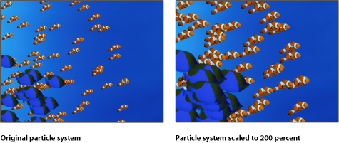
For particle systems containing multiple cells, the Emitter HUD parameters simultaneously modify the effect of each cell’s parameters relative to one another. This means that for a particle system consisting of two cells with different scale values, changing the scale in the HUD resizes both cells simultaneously. For example, increasing the scale in the HUD by 200% does not change the scale of both cells to 200%, but resizes the cells relative to their original scale values.
For this reason, in emitters with multiple cells, the HUD parameters are displayed as percentages. When you modify the parameters of a single cell, the cell parameters are adjusted directly.
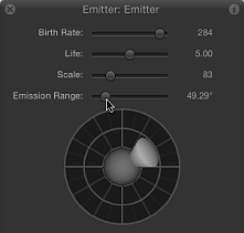
- Emission Control: A graphical control that lets you modify several parameters simultaneously, described below:
- Emission Range (2D only): Drag the two points on the outer ring of the graphical emission control to define the range of degrees at which particles are generated. In other words, the Emission Range parameter defines the size of the “slice” of the pie graph that the particles fill when generated. This graphical control adjusts the same parameter as the Emission Range slider.
- Emission Speed (2D only): Drag the blue arrows outward or inward to define how quickly particles move away from the emitter.
Use the following modifier keys to more precisely manipulate the graphical emission control in the HUD:
- Shift (while adjusting Emission Angle): Restricts angles to 45 degree increments.
- Shift (while adjusting Emission Range): When working with a 2D emitter, restricts to 22.5-degree increments.
- Command: When working with a 2D emitter, adjusts Emission Angle only.
- Option: When working with a 2D emitter, adjusts Emission Speed only.
- Emission Latitude/Emission Longitude Control (3D only): When using a 3D particle emitter (when the 3D checkbox is selected in the Emitter Inspector), the emission control of the HUD lets you modify the Emission Latitude and Emission Longitude parameters.
Drag the sphere in the center of the circle to modify the emission direction (in degrees latitude and longitude) of the particles. You can also enter specific values in the Emitter Inspector.
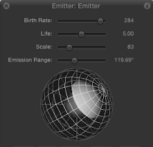
Drag the Emission Range slider (above the sphere) to define the range of degrees at which particles are generated. In other words, this control defines the size of the cone that the particles fill when generated in 3D space.
Particle Emitters and the Properties Inspector
Emitter parameters can also be modified in the Properties Inspector. The following sections briefly discuss using some of the parameters in the Properties Inspector with a particle system (not all parameters in the Properties Inspector are discussed). For more information on the Properties Inspector parameters, see Parameters in the Properties Inspector.
Note: When a particle cell is selected, only the Timing parameter appears in the Properties Inspector. This allows you to control the In and Out points of the particle cell.
Important: Some operations that can be performed in the Properties Inspector, as well as the application of certain filters or a mask, cause a group to be rasterized. Rasterization can affect the way that layers in Motion (including particle systems) behave. For more information, see About Rasterization.
Transform Parameters
As a particle system plays, the cells in the system are duplicated, according to the parameters for that system, to create each particle in the Canvas. Because all particles emerge relative to the position of the emitter, changing the emitter’s position in the Canvas also changes the position of every particle in that system.
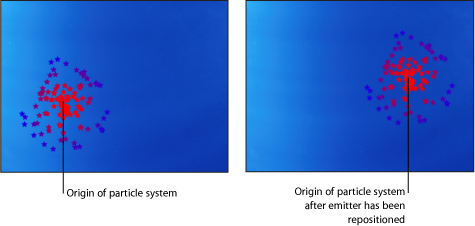
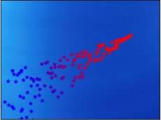
This rule of thumb has one exception: For an emitter whose position is animated using a behavior or keyframes, particles move relative to their position at the time of their release, regardless of changes to the emitter’s position in subsequent frames. In the example shown below, an animated emitter moves across the screen leaving a trail of particles that maintain their original trajectory, regardless of the changing emitter position.
The Attach to Emitter parameter in the Particle Cell Inspector modifies this behavior. When set to 0%, the particles are completely independent of the emitter. When set to 100%, the particles try to keep up with the position of the animated emitter. Depending on any applied behaviors, such as Drag, the particles might not be able to keep up with the emitter.
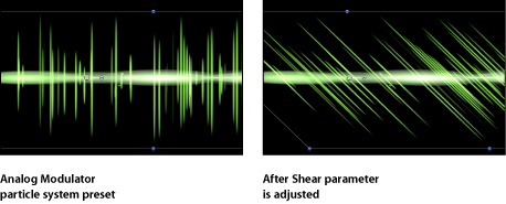
Modifying an emitter’s other transformation parameters (Rotation, Scale, Shear, and Anchor Point) changes the distribution of particles from that emitter and transforms each particle. For example, if you create an emitter, then modify its Shear parameter, the distribution of the emitted particles changes to reflect the new plane of the emitter, and the particles are sheared along the same plane.
Blending
Any changes you make to the opacity or blend mode parameters for an emitter are applied to the particle system as a whole. For more information about blend modes, see Using Blend Modes. For more information about the Preserve Opacity setting, see Preserve Opacity Option.
Note: In the emitter, the particles can be blended additively or normally (using the Additive Blend checkbox in the Particle Cell Inspector).
Lighting
A 2D or 3D emitter can interact with lights in a 3D project. The Shading pop-up menu (in the Lighting section of the emitter’s Properties Inspector) must be set to On or Inherited for the lights to affect the particles. For more information on using lights, see Lighting.
Shadows
A 2D or 3D emitter can cast and receive shadows in a 3D project. If the 3D checkbox is selected in the Emitter Inspector, the Render Particles pop-up menu (underneath the 3D checkbox) must be set to In Global 3D (Better) for particles to cast shadows. For more information on using shadows, see Shadows.
Reflections
A 2D or 3D emitter can cast reflections in a 3D project, but only a 2D emitter can receive reflections. For more information on using reflections, see Reflections.
Note: When the 3D checkbox in the Emitter Inspector is selected, the Reflection controls do not appear in the Properties Inspector.
Drop Shadow
Drop shadows can be applied to a 2D particle system, to the emitter as a whole, or to the individual particles in the system. To apply a drop shadow to the emitter as a whole, select the emitter, then select the Drop Shadow activation checkbox in the Properties Inspector.
Note: The Drop Shadow parameter is not available in the Properties Inspector for the emitter when the Box or Sphere emitter shape, or the 3D checkbox, is selected in the Emitter Inspector.
To apply drop shadows to individual particles in the system, select the (dimmed) source object in the Layers list, then select the Drop Shadow activation checkbox in the Properties Inspector. For more information on working with drop shadows, see Drop Shadows.
Timing
When you create a particle system, its duration can be as long or short as necessary, regardless of the duration of the original source objects used to create the particle system. The duration of a particle system is defined by the duration of the emitter object. Changing the In or Out point of an emitter in the Properties Inspector, Timeline, or mini-Timeline changes the duration of the entire particle system.
By default, particles are generated by every cell in a system for the duration of the emitter. The duration of each generated particle is defined by the Life parameter of the cell that generated it, and not by the duration of the cell itself.
The duration of the cell controls the duration over which new particles are generated. You can change a cell’s duration by dragging its position or its In and Out points in the Timeline. In this way, you can adjust the timing that defines when each cell’s particles emerge.
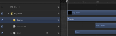
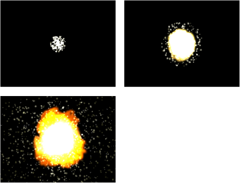
For example, you can create a particle system that simulates an explosion by offsetting the appearance of three types of particles. First, dense white sparks emerge from the center. Half a second later, more diffuse orange blast particles appear around a larger area. One second after that, hot smoke emerges from underneath both of these layers as they fade away.
You can offset a cell in the Timeline or mini-Timeline to start before the emitter. This creates a “preroll” in which the particle simulation starts before the particles are drawn.
For more information on adjusting the timing of layers in the Timeline, see Using the Timeline.