Particle System Examples
This section presents two examples of how to use particle systems to create very different effects. The particle system created in the second example is turned into a 3D particle system after the “pixie dust” is animated.
Tip: You can use the Make Clone Layer command to clone an emitter and then use the Retiming controls or Retiming behaviors to create unique animations. For example, you can create a starburst that explodes outward, then retracts, then explodes, and so on. For more information on cloning, see Making Clone Layers.
Example 1: Creating an Animated Background
This first example describes how to create an animated background using a single still image. By using the parameters available in the Emitter Inspector, a single image can be turned into a complex animated texture.
Drag a file into the Canvas.
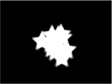
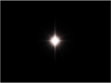
This example uses a simple star graphic.

With the new layer selected, click the Make Particles button in the toolbar (or press E).
When you add an emitter to the project, the following occurs:
The emitter appears in the Layers list and is selected.
A cell containing the image to be “particle-ized” appears underneath the emitter.
The original source layer (cell source) is disabled.
In the Canvas, the emitter bounding box appears, which can be transformed using the onscreen controls.
The first particle appears in the Canvas in the same location as the original object. Although it appears as if the particle is selected, it is the bounding box for the emitter.
The Emitter HUD appears. If you have hidden the HUD, press D or F7.
Note: For projects with a frame rate greater than 30 fps, at times only the bounding box (not the particle cell) might appear at the first frame of your project. Because particles are generated at a rate of 30 per second, there is no guarantee a particle will appear on every frame.
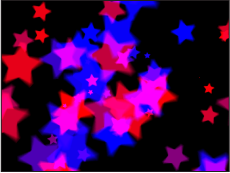
In the Emitter Inspector, choose Circle from the Shape pop-up menu.
Choose Tile Fill from the Arrangement pop-up menu.
In the Cell Controls section of the Emitter Inspector, set the Initial Number parameter to 12.
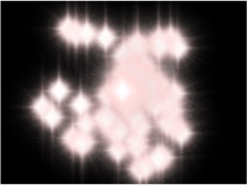
This creates a distributed group of particles that partially fills the Canvas.
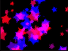
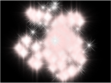
To turn the particles into a uniform abstract mass, adjust the following parameters:
Set Life to 4.
Set Speed to 140.
Set Spin to 60.
Set Spin Randomness to 15.
Select Additive Blend.
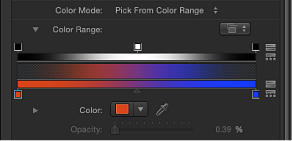
Set Color Mode to Pick From Color Range. (Or, if you prefer, select another gradient from the preset pop-up menu.)
Set Scale to 65%.
Set Scale Randomness to 150.
Set Random Seed to 10000.
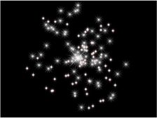
Advance to frame 100.
The resulting image now looks similar to this:
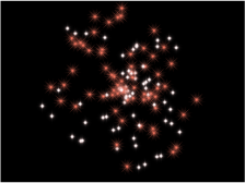
Apply a filter to the emitter.
In this example, adding the Crystallize filter creates an even more abstract effect. You might also consider adjusting the color gradient, or applying color correction to make the background fit more appropriately with your foreground elements.
Adjust the Color Range opacity gradient so the particles fade in and out rather than popping into and out of existence.
Example 2: Creating Animated Pixie Dust
This example shows you how to create a particle system that uses two different cells to generate a streak of particles that trails behind another animated layer. Using two cells adds more variation to a particle system than can be achieved with a single set of cell parameters.
Drag the first image file into the Canvas.
This example uses the “Flare01” image from the Particle Images subcategory in the Content category of the Library. This is a small image of a lens flare against black, with a built-in alpha channel.
With the flare object selected, click the Make Particles button in the toolbar (or press E).
An emitter is added to the project, but nothing happens yet because the playhead is at the first frame of the project, and only one particle has been created. Move the playhead forward a few seconds to view the particle system at a frame where more particles have been generated. You can also play the project while you make your modifications to the particle system.
To create a variety of particles, drag additional image layers onto the emitter you just created.
This example uses the “Spark12” file, also located in the Content folder in the Library.
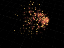
This results in the following image:
To make the particles generated by each different cell mingle together, select the Interleave Particles checkbox in the Emitter Inspector.
Select the “Flare01” cell in the Layers list, then set the Scale slider in the Particle Cell Inspector to 15%.
Doing this reduces the size of the particles generated by this cell.
Select the “Spark12” cell in the Layers list, then set the Scale slider in the Inspector to 45%.
The resulting image should look approximately like this:
Note: If necessary, disable the original “Spark12” source layer.
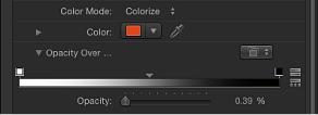
Next, change the color of the particles generated by the “Spark12” cell by doing the following:
Choose Colorize from the Color Mode pop-up menu.
Click the color well in the Color section of the Inspector and choose a light red color in the Colors window.
Close the Colors window.
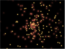
All particles generated by that cell are now red.
Use the Opacity Over Life control to make this cell’s particles fade out over their life.
To make the spark particles spin as they move away, set the Spin parameter value to 60.
In the Layers list, select the “Flare01” cell of the particle system. Its parameters appear in the Inspector.
Follow the procedure in Step 7 to make these particles light yellow.
To make the particles generated from this cell spin in the opposite direction, set the Spin parameter value to –60.
To create a trail of particles, the emitter must be animated to follow the required motion path; do the following to create a motion path for the particle system:
Place the playhead at frame 1.
Click the Record button (or press A) to turn on animation recording.
Note: As an alternative to Step B (turning on the Record button), you can manually add a keyframe to the emitter’s Position parameter in the Properties Inspector after Step C. Any subsequent changes to the emitter’s position result in a keyframe at the current playhead position (regardless of the Record button state).
Select the emitter and drag the particle system to the lower-left corner of the screen.
Press End to go to the last frame of the project.
Drag the emitter toward the upper-right corner.
Disable Record (press A).
Click the Play button to begin playback.
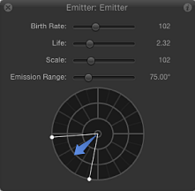
Use the following illustration as a guide to adjust the Emission Range and Angle so the particles appear to follow behind the emitter.
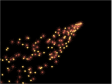
The result should look something like this:
You might want to adjust the Emitter parameters for Birth Rate, Life, and Speed to customize the effect to your liking.
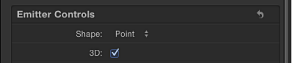
In the Emitter Inspector, select the 3D checkbox.
If your project does not contain a camera, click the New Camera button in the toolbar.
If your project is a 2D project, a dialog appears asking if you want to switch your 2D groups to 3D.
Click Switch to 3D.
A camera is added to the project, and your layers are turned into 3D layers.
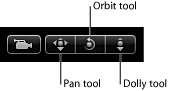
In the 3D View tools (in the upper-right corner of the Canvas), drag the Orbit tool (the center tool).
As the camera rotates, you can see that the particles are emitted in Z space.
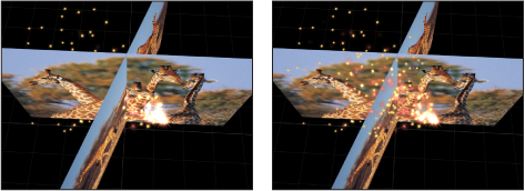
If you want your particles to intersect with other rotated layers, choose In Global 3D (Better) from the Render Particles pop-up menu in the Emitter Inspector. In the following image on the left, Global 3D is selected so the particles intersect with other objects in the project that are transformed in 3D space. In the image on the right, Local 3D is selected so the particles do not intersect with other objects.