Adjusting Layer Properties in the Inspector
Manipulating an onscreen transform handle also changes the corresponding parameter in the Properties Inspector. If you want to transform a layer more precisely than the onscreen controls allow, you can change that parameter’s value in the Properties Inspector.
When you select a single layer and open the Properties Inspector, the layer’s parameters are displayed. Making changes to the values in the Properties Inspector affects the selected layer. If more than one layer is selected in the Canvas, Layers list, or Timeline, the parameter values displayed in the Properties Inspector become inaccessible. However, you can still adjust the onscreen controls. Manipulating an onscreen transform handle affects every selected layer equally.
Select a parameter value field, enter a new number, then press Return.
If the parameter has a graphical control, such as a slider or dial, adjust the control.
To reset a parameter to its default state, click its reset button, or choose Reset Parameter from the parameter’s Animation menu.
Drag left on the parameter value to decrease, or right to increase the value.
For more information on how to use the parameter controls, see User Interface Controls.
Parameters in the Properties Inspector
The Properties pane of the Inspector displays the following parameters for most layers and groups:
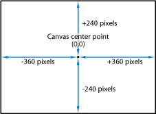
- Position: Defines the X (horizontal), Y (vertical), and Z (depth) position of each layer.
The coordinate system used by Motion specifies the center of the Canvas as 0, 0, 0 regardless of the frame size of the project. Moving a layer to the left subtracts from the X value, while moving to the right adds to the X value. Moving a layer up adds to the Y value, and moving a layer down subtracts from the Y value. Moving a layer closer adds to the Z value, while moving further away subtracts from the Z value.
Each layer’s position is centered on its anchor point. Offsetting the anchor point also offsets the position of the layer relative to the X, Y, and Z position values you have set.
- Rotation: A dial that controls a one-dimensional value representing the number of degrees of rotation around the Z axis. A positive value rotates the layer counterclockwise. A negative value rotates the layer clockwise.
Rotating a layer beyond 360 degrees results in multiple rotations when the Rotation parameter is animated.
Click the disclosure triangle next to the Rotation parameter to reveal dials that adjust rotation around all three axes (X, Y, and Z), as well as the Animate pop-up menu.
- Animate: Allows you to set the interpolation for animated 3D rotation channels to one of two options:
Use Rotation: The default interpolation method. Layer rotates from its start angle to their final angle. Depending on the animation, the layer might twist before reaching its final orientation (the last keyframed value). For example, if the X, Y, and Z Angle parameters are animated from 0 degrees to 180 degrees in a project, the layer rotates on all axes before reaching its final orientation.
Use Orientation: This alternate interpolation method provides smoother interpolation but does not allow multiple revolutions. Use Orientation interpolates between the layer’s start orientation (first keyframe) to its end orientation (second keyframe).
Note: The Rotation parameter must be keyframed for the Animate parameter options to have any effect.
- Scale: A slider that controls the percentage representing the layer’s scale, relative to its original size. By default, the horizontal and vertical scale of a layer is locked to the layer’s original aspect ratio—represented by a single percentage. Click the disclosure triangle to display independent percentages for the X, Y, and Z scales of the layer.
Note: Setting a layer’s scale to a negative value flips the layer.
- Anchor Point: Value sliders that define the X and Y position of the anchor point relative to the center of the layer. Coordinates of 0, 0 center the anchor point in the bounding box defining the outer edge of the layer. Click the disclosure triangle to expose an additional value slider defining the Z position.
- Opacity: A slider that sets the transparency of the layer. For more information, see Editing Opacity and Blending Parameters.
- Blend Mode: A pop-up menu that sets the Blend Mode of the layer. For more information, see Editing Opacity and Blending Parameters.
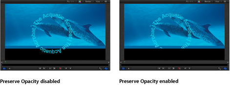
- Preserve Opacity: When this checkbox is selected, the layer appears only where another layer is visible behind it in the composite. The front layer uses the opacity value of the layer behind it. For more information, see Preserve Opacity Option.
- Casts Reflections: A pop-up menu that determines whether a layer casts a reflection. Choose from three options:
Note: Reflections are only visible when layers are in a 3D group. For more information on 3D groups, see 3D Group Properties.
- Yes: The layer is seen reflected in nearby reflective layers.
- No: The layer is ignored by reflective surfaces.
- Reflection Only: The layer becomes invisible, but will appear in reflective surfaces around it.
The following three parameter groups in the Properties Inspector—Lighting, Shadows, and Reflection—appear only when the parent group is set to 3D.
- Highlights: When this checkbox is selected, lit layers in the scene show highlights. This parameter has no effect if Shading is set to Off. Click the disclosure triangle to reveal an additional Shininess parameter.
- Shininess: A slider that sets how strong a layer’s highlights appear. Higher values create a glossier appearance.
For more information on using lights, see Lighting.
- Shadows Only: A checkbox that, when selected, specifies that a layer blocks light and casts a shadow, while the layer itself does not appear in the scene.
Note: For more information on using shadows, see Shadows.
- Falloff: A checkbox that controls whether the reflection fades with distance from the layer, producing a more realistic result. Click the disclosure triangle to show additional controls that adjust the falloff effect: Begin Distance, End Distance, and Exponent. The Exponent slider adjusts how quickly the reflection becomes fainter as reflected layers move away from the reflecting layer.
- Blend Mode: A pop-up menu that determines the blend mode used for the reflection.
Note: For more information on using reflections and their parameters, see Reflections.
- Drop Shadow: Turns the drop shadow of a layer on and off. For more information about working with drop shadows, see Drop Shadows.
- Four Corner: Click the activation checkbox to turn distorting on and off. If a layer is distorted and this checkbox is deselected, the layer resumes its original shape, although the distorted coordinates are maintained. Reselecting the checkbox re-enables the distort effect specified by the Four Corner coordinate parameters.
Value sliders modify the X and Y coordinates of the layer’s four corner points (Bottom Left, Bottom Right, Top Right, and Top Left).
You can also control these parameters visually in the Canvas using the Distort tool. For more information, see 2D Transform Tools.
- Crop: Click the activation checkbox to turn cropping on and off. If a layer is cropped and this checkbox is deselected, the layer resumes its original size, although the cropping values are maintained. Reselecting the checkbox re-enables the cropping effect specified by the crop parameters.
Adjust the four sliders to modify the crop parameters. Each slider defines the number of pixels to be cropped from the layer’s four sides, relative to the outer edge of the bounding box that surrounds it. These parameters are similar to the crop parameters in the Media Inspector (available when you select a layer in the Media list). However, whereas cropping a layer via the Media Inspector crops all instances of that layer in your project, cropping a layer in the Properties Inspector crops only a single instance of the layer; duplicates of the layer remain uncropped. For more information, see Media Inspector.
- Timing: These parameters control all aspects of clip retiming. For more information, see Retiming.