3D Transform Tools
There is no inherent difference between 2D and 3D project files in Motion. At any point, you may decide to start working with groups or layers in 3D. Doing so requires no preplanning on your part; in fact, it’s possible to go back and forth between manipulating objects in 2D and 3D space. This section covers the tools you can use to move objects around in the Canvas.
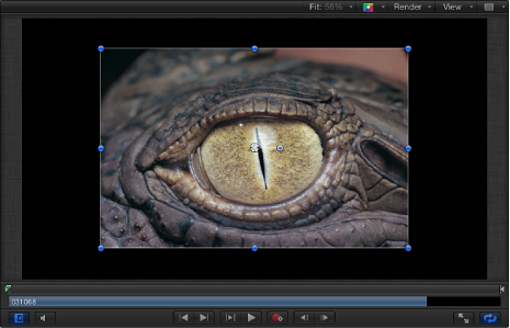
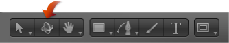
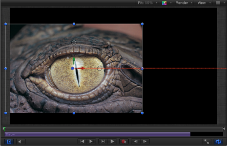
The image in the screenshot above has just been imported into the scene and is positioned at the scene’s origin. Use the 3D Transform tool—located to the right of the 2D transform tools in the toolbar—to move the image.
Tip: You can select the 3D Transform tool by pressing Tab when the 2D Select/Transform tool is active (and an object is selected in the Canvas). Pressing Tab again cycles through the various 2D transform tools.
Select the 3D Transform tool in the toolbar (or press Q).
Two things happen immediately when you select the 3D Transform tool. The onscreen controls change, and the object’s HUD displays additional 3D transform controls.
3D Transform Onscreen Controls
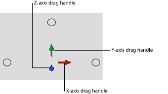
When you select the 3D Transform tool, three colored arrows appear in the Canvas near the center of the image. Each arrow corresponds to one of the three coordinate axes. In the default view, the Z axis points directly toward you, so only the tip of the blue Z arrow is visible. Dragging an arrow moves the image along an axis.
Select the object to move.
Drag a colored arrow.
When dragging, the active arrow turns yellow and the status bar above the Canvas displays the current coordinates of the object as well as the distance the object has moved. Coordinates are given in the form of X, Y, and Z.
Near the three colored arrows are three small circles.
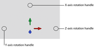
These are rotation handles. Placing the pointer over a circle invokes a rotation ring for the axis.
Select the object to rotate.
Move the pointer to the rotation handle (small circle) corresponding to an axis of rotation.
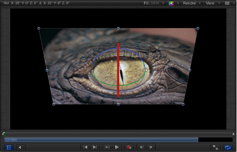
The rotation ring appears.
Drag the ring to rotate the object.
The status bar displays the current Rotation values as well as the amount the object is rotated.
Select the object to rotate.
Place the pointer on a rotation handle, then hold down the Command key.
All three rotation rings appear.
While continuing to hold down the Command key, drag anywhere inside the rings to rotate the object.
The status bar displays the absolute rotation values as well as the delta (amount of change) in rotation.
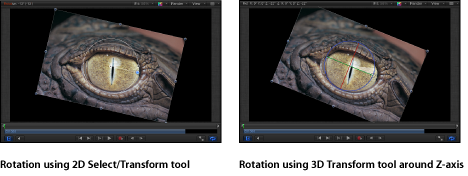
Important: Rotation performed with the 2D Select/Transform tool is only around the Z axis.
3D Transform HUD Controls
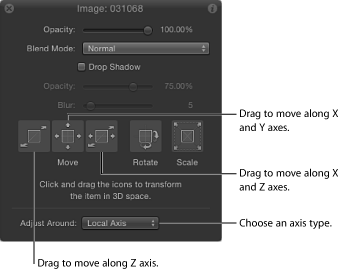
In addition to the onscreen controls, the HUD provides another method of transforming objects in 3D space, using a set of graphical transform controls.
- Move: Three controls in the Move section of the HUD let you drag the selected object in one or more axes at once. Drag inside a Move control to change the relevant parameter values of the object in the Canvas.
- Move Z: Drag here to move the selected object along the Z axis. Dragging to the right decreases the Z value (moving the object further away), and dragging to the left increases the Z value (bringing the object closer). Hold down the Command key when dragging to simultaneously scale the object as it is moved, preserving its size relative to the camera.
- Move XY: Drag here to move the object along the X and Y axes. Dragging right or left increases or decreases the X value. Dragging up or down increases or decreases the Y value. Using this control is identical to draggin a 2D object in the Canvas. Hold down the Command key when dragging to constrain movement to the initial direction of the drag.
- Move XZ: Drag here to move the object along the X and Z axes. Dragging right or left increases or decreases the value of X. Dragging up or down increases or decreases the value of Z. Hold down the Command key when dragging to constrain movement to the initial direction of the drag.
Tip: As in the Inspector, holding down the Shift key while you drag in the HUD makes larger changes. Holding down the Option key while you drag makes smaller changes.
- Rotate and Scale: Two additional drag controls in the HUD let you rotate and scale the selected object in the Canvas:
- Rotate XYZ: Drag here to rotate the object around all axes. Starting at the origin, dragging up and down rotates the object around the X axis. Dragging to the left and right rotates the object around the Y axis.
To constrain rotation to the Z axis, hold down the Command key while dragging.
- Scale: Drag here to uniformly scale the selected object in the Canvas. Dragging to the right or up (or both) increases the Scale value. Dragging to the left or down (or both) decreases the Scale value.
To constrain scaling to the axis corresponding to the initial direction of the drag, hold down the Command key while dragging.
- Adjust Around: The Adjust Around pop-up menu, located under the Move, Rotate, and Scale controls in the HUD, allows you to select which relative coordinate space is used for transforms. The Adjust Around pop-up menu has three options:
- Local Axis: The default, this option orients the onscreen transform controls to the object’s local axes.
- World Axis: This option orients the onscreen transform controls to the axes of the 3D grid in the Canvas.
- View Axis: This option orients the onscreen transform controls to the view space of the current view. The Z axis is aligned along the view’s line of sight. For more information on views, see Views.
Relative Coordinates
To better understand the concept of relative coordinates, think of a system of satellites, like the earth, the moon, and the sun. The moon’s parent is the earth, and the earth’s parent is the sun. Usually, when considering these three bodies, the moon’s position is described in terms of its position relative to the earth (the moon’s parent), and the earth’s position is described relative to the sun (the earth’s parent). In Motion, an object’s position and orientation are always relative to its parent.
When you add a group to a Motion project, that group is created at the origin coordinates of its parent. In the case of a root-level group (a group that is not nested inside other groups in the Layers list), the parent is the project itself. An object placed inside a group has its position described relative to its parent: the group.
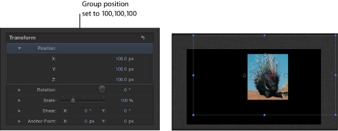
In the example above, a group is positioned at X, Y, and Z coordinates of 100, 100, and 100, respectively. The group is located 100 pixels away from its parent’s origin on all axes (the parent in this case being the project itself). The image inside the group is positioned at 0, 0, 0. Because the image’s position is relative to its parent, the group, it shares its parent’s origin and has an apparent position in the world of 100, 100, 100.
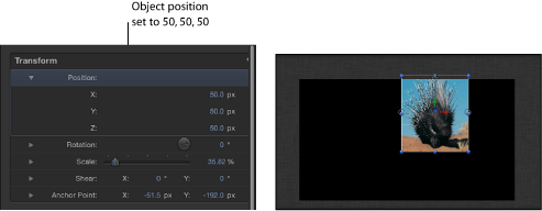
Moving the image to a position of 50, 50, 50 displaces it by 50 pixels from the group’s origin in all axes. You can see in the image below that the porcupine is now exceeding the visible area of the Canvas. Although the image’s apparent position relative to the world is 150, 150, 150, its Position values in the Inspector are 50, 50, 50 because its position is always relative to its parent.
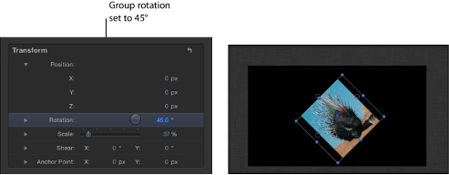
Rotation values are also relative to an object’s parent.
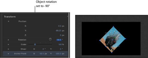
Important: World and view transforms are limited to the HUD and onscreen controls; all transforms made in the Inspector are relative to an object’s parent’s space.
Layer Order and Depth Order
When compositing in 2D, the Layers list shows the layer order, which determines the stacking order of objects in the Canvas. Objects higher up in the Layers list appear in the Canvas on top of objects lower than them in the Layers list.
Important: The children of 2D groups are composited in layer order.
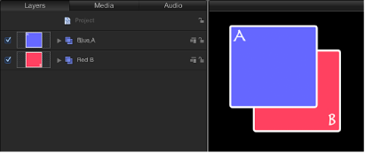
In the following example, the Layers list shows the Blue A group is above the Red B group, and the Canvas displays the Blue object above the Red one.
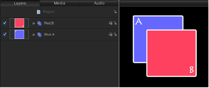
If you move Group A below Group B in the Layers list, Group B is rendered on top of Group A.
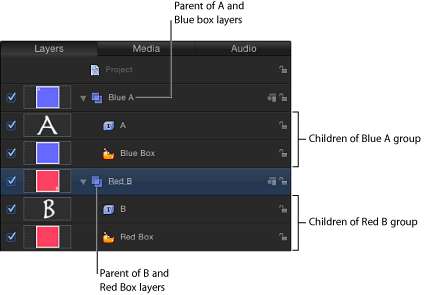
The Layers list also shows object relationships in terms of parenting. The parent-child relationship is displayed in the Layers list through the use of indenting and disclosure triangles.
The Layers list is not the only indicator of order when considering objects in 3D. When depth-sorted, an object can be at the bottom of the Layers list and yet appear to be on top of everything else in the Canvas, because of the object’s position relative to the current camera. The most common way to adjust depth order is to change the Z position of a layer or group.
Important: The children of 3D groups are composited in depth order by default.
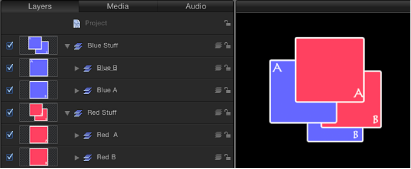
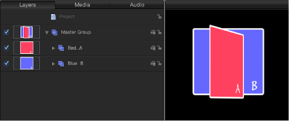
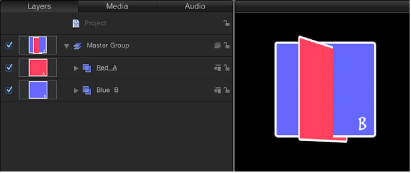
With the 3D groups above, objects are composited in depth order; their position in the Layers list does not correlate to their position in 3D space relative to the camera.
In the above example, the Blue A group is above the Red A group in the Layers list but it appears behind the Red A group in the Canvas because it is depth-sorted. The same principle applies to the Blue B group and the Red B group.
3D Transformations in 2D Groups
All objects have 3D transformations available, even when in 2D groups. Objects can be rotated around any axis and moved along any axis. Objects in 2D groups are not depth-sorted, and cannot intersect, regardless of their position in 3D space.
In the image below, groups A and B are positioned at the same point in 3D space. But because they are layer-ordered, group A does not intersect with group B.
However, when you change the parent group to 3D, groups A and B intersect, as shown in the image below.
Note: If two groups are coplanar (occupy the same plane), they are composited in layer order, regardless of whether the objects’ parent is a 2D group or 3D group. In a 2D composite, all objects are coplanar.