Emitter and Cell Parameters
Several parameters in the Emitter Inspector are identical to those found in the Emitter HUD, with one difference: Although the emission control in the Emitter HUD allows you to manipulate the Range, Angle, Latitude (3D), Longitude (3D), and Speed parameters using a single, graphical control, the Emitter Inspector uses individual controls for each parameter.
Note: There is no way to control the animation of individual particles.
Important: The emitter parameters in the Properties and Emitter Inspectors can be keyframed to change values over time.
Emitter Parameters in the Inspector
These parameters (in the Emitter Controls group) determine how particles are distributed and rendered in your project. The Emitter Inspector has a large number of parameters, some of which depend on the settings of other parameters in the Inspector. All combinations of parameters are described below.
- Shape: The first parameter in the Emitter Inspector is the Shape pop-up menu. When 3D is turned off, nine options are available. When the 3D checkbox is selected, two additional shapes become available. Different shapes significantly alter the distribution of generated particles. When you choose an emitter shape, different Emitter Inspector parameters appear that are unique to that shape. For example, when Rectangle is the selected shape, Outline, Tile Fill, and Random Fill become available in the Arrangement options. When Spiral is the selected shape, the Arrangement parameter goes away and new parameters such as Radius, Number of Arms, and Twists become available. These different parameters provide additional control over the distribution of particles.
In addition, when the 3D checkbox is selected, the Render Particles, Emission Latitude, Emission Longitude, and Depth Ordered parameters become available for all emitter shapes.
- Point: This is the simplest emitter shape and is the default shape for new emitters. It specifies a single point of emission for a particle system. There are no additional parameters for the Point shape.
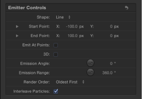
- Line: Particles emerge from a line. Using the onscreen controls (with the Adjust Item tool) or the Properties Inspector, you can specify the length and location of the line. In the Inspector, you can set a specific number of points where particles emerge. This emitter shape is good for creating sheets of particles that cascade over a wide area. The Line shape displays additional parameters.
- Rectangle: Particles emerge from a rectangle along its edge, or in a tile-fill or random-fill pattern. Using the onscreen controls (with the Adjust Item tool), you can specify the size and location of the rectangle. Drag the corners to adjust width and height; drag edges to adjust width or height independently. Depending on the selected Arrangement, the Rectangle emitter shape displays additional parameters. In the following image, the Emitter shape Arrangement parameter is set to Outline.

Use the following modifier keys to more precisely manipulate the corners of the Rectangle onscreen controls (with the Adjust Item tool):
- Option: Adjustments to size are scaled uniformly, with the anchor point remaining fixed.
- Shift: Adjustments to size are made proportionally.
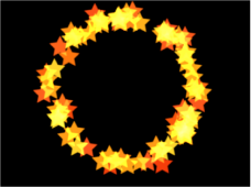
- Circle: Particles emerge from a circle-shaped emitter. Particles can be emitted in an outline, tile-fill, or random-fill pattern. This emitter shape is good for surrounding an element in a composition with particles that emerge from its edge. Using the onscreen controls (with the Adjust Item tool), you can specify the size and location of the circle. Depending on the selected Arrangement, the Circle emitter shape displays additional parameters. In the following image, the shape’s Arrangement parameter is set to Outline.
- Burst: Particles emerge from a burst pattern. Using the onscreen controls (with the Adjust Item tool), you can specify the size and location of the burst. The Burst shape displays additional parameters.
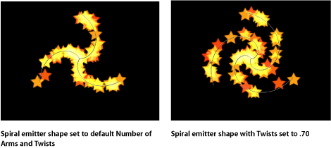
- Spiral: Particles emerge from a spiral pattern. Using the onscreen controls (with the Adjust Item tool), you can specify the size and location of the spiral. The Spiral shape displays additional parameters.

- Wave: Particles emerge from a waveform. Using the onscreen controls (with the Adjust Item tool) or the Start Point and End Point parameters in the Emitter Inspector, you can specify the length and location of the wave. The Wave shape displays additional parameters.

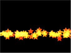
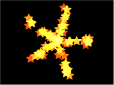
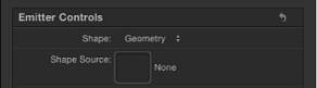
- Geometry: Particles emerge from the edge of a shape, defined by a spline object used as the shape source. The Geometry shape displays additional parameters. The following image on the right shows the shape used as the emitter source. The image on the left shows particles emerging from the edge of the shape source.

To apply a shape as the geometry shape source for a particle emitter, drag the shape to the Shape Source well in the Emitter Inspector (after Geometry is chosen from the Shape pop-up menu).
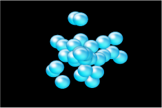
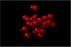
- Image: Particles emerge from within an area defined by an image or from only the edges of the image. The image may or may not have an alpha channel. If it does, the shape of the alpha channel can also be used to define the emitter shape. The Image shape displays additional parameters. The following image on the right shows the image used as the emitter image source. The image on the left shows the particles emerging from within the image.
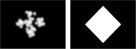
To apply an image as the image source for a particle emitter, drag the image to the Image Source well in the Emitter Inspector (after Image is chosen from the Shape pop-up menu).
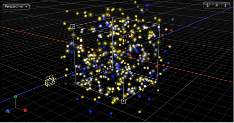
- Box: This option is available when the 3D checkbox is selected in the Emitter Inspector. Particles are emitted from a three-dimensional cube along its surface (Outline), or in a tile-fill or random-fill pattern. Using the onscreen controls (with the Adjust Item tool), you can specify the size and location of the rectangle. Drag the front horizontal edge to adjust height; drag the front vertical edge to adjust width; drag a back edge to adjust depth; drag a front corner to simultaneously adjust the width and height. To reposition the emitter, drag in the shape (but not on an edge or corner point). Depending on the selected Arrangement, the Box shape displays additional parameters. In the following image, the box’s Arrangement is set to Tile Fill.
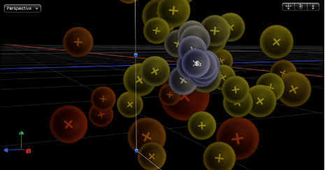
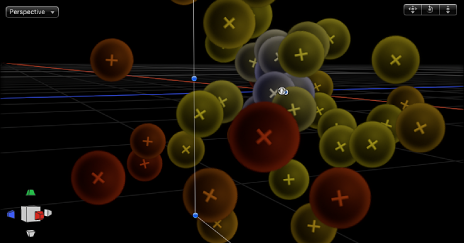
- Sphere: This option is available when the 3D checkbox is selected in the Emitter Inspector. Particles are emitted from a three-dimensional sphere along its surface (Outline), or in a tile-fill or random-fill pattern. Using the onscreen controls (with the Adjust Item tool), you can specify the radius and location of the sphere. Drag the outline of the sphere to adjust its radius; drag in the sphere to reposition it in the Canvas. When Sphere is selected, the Arrangement parameter becomes available. Depending on the selected Arrangement, the Sphere shape displays additional parameters.
- Arrangement: This pop-up menu, available when Rectangle, Circle, Image, Box, or Sphere is chosen in the Shape pop-up menu, specifies the pattern from which the particles are generated. The arrangement options are:
- Outline: Emits particles along the edge of the shape in 2D emitters and along the surface of the shape in 3D emitters.
- Tile Fill: Emits particles from a tiled pattern of rows, columns, and ranks (for 3D emitters) in the circle, rectangle, image, box, or sphere. You can specify the number of columns, rows, and ranks, as well as the Tile Offset.
- Random Fill: Emits particles randomly from within the circle, rectangle, image, box, or sphere.
- Size: This slider becomes available when Rectangle or Box is chosen in the Shape pop-up menu. Defines the size of the rectangle or cube from which particles are emitted. The Size slider is available whether the Arrangement is set to Outline, Tile Fill, or Random Fill. When Rectangle is the selected shape, the Width and Height parameters become available. When Box is selected, an additional Depth parameter is available.
Note: The Height is measured in project pixels; however, the Width is measured in square pixels. This is done so a shape that is numerically square will look square when Correct for Aspect Ratio is turned on (checkmarked) in the View pop-up menu in the top-right corner of the Canvas.
- Columns: This slider becomes available when one of the following is chosen in the Shape pop-up menu: Rectangle, Circle, Image, Box, or Sphere; in addition, Arrangement must be set to Tile Fill. This parameter specifies the number of horizontal emitter points on a grid over the selected emitter shape. In the case of an irregular shape (nonrectangular), grid points that fall outside of the shape are ignored.
- Rows: This slider becomes available when one of the following is chosen in the Shape pop-up menu: Rectangle, Circle, Image, Box, or Sphere; in addition, Arrangement must be set to Tile Fill. This parameter specifies the number of vertical emitter points on a grid over the selected emitter shape. In the case of an irregular shape (nonrectangular), grid points that fall outside of the shape are ignored.
- Tile Offset: This slider becomes available when one of the following is chosen in the Shape pop-up menu: Rectangle, Circle, Image, Box, or Sphere; in addition, Arrangement must be set to Tile Fill. Values from 0 to 100% offset the rows toward the right, and values from 0 to –100% offset the rows toward the left. A value of 50 or –50% creates a “brickwork” pattern.
- Emission Alpha Cutoff: This slider becomes available when Image is chosen in the Shape pop-up menu. When the Image Source object contains an alpha channel, this slider defines the minimum opacity value necessary to create particles at that point on the source image. For example, when set to 25%, particles appear only where the alpha value of the image is equal to or greater than 25% opacity. The lower the Emission Alpha Cutoff value, the more particles appear. For this parameter to be effective, the alpha channel must have areas of varying transparency.
- Start Point: This parameter, which becomes available when Shape is set to Line or Wave, consists of two value sliders that define, in X and Y coordinates, the first point of the line used as the emitter shape. Click the disclosure triangle to modify the Z position of the start point. You can adjust these values in the Canvas using the onscreen controls (with the Adjust Item tool).
- End Point: This parameter, which becomes available when Shape is set to Line or Wave, consists of two value sliders that define, in X and Y coordinates, the second point of the line used as the emitter shape. Click the disclosure triangle to modify the Z position of the start point. You can adjust these values in the Canvas using the onscreen controls (with the Adjust Item tool).
- Emit At Points: This checkbox is available when any of the following is chosen in the Shape pop-up menu: Line, Rectangle (with Arrangement set to Outline or Random), or Circle (with Arrangement set to Outline or Random), Burst, Spiral, Wave, Geometry, Box (with Arrangement set to Outline), or Sphere (with Arrangement set to Outline). When the Emit At Points checkbox is selected, particles emerge from a limited number of points (as defined in the Points parameter). When the checkbox is deselected, particles may emerge from anywhere on the line or edge. When the Adjust Item tool is selected, the points become visible in the Canvas. When Emit At Points is selected, two additional parameters become available: Points and Offset.
- Points/Points Per Arm: This slider becomes available when any of the following is chosen in the Shape pop-up menu: Line, Rectangle, Image, or Circle (with Arrangement set to Outline or Random Fill), Burst, Spiral, Wave, or Geometry; in addition, the Emit At Points checkbox must also be selected. Defines the number of points where particles are emitted. For Rectangle or Circle shapes, the particles are emitted from evenly distributed points along the edge of the shape when Outline is chosen from the Pattern pop-up menu. When the Adjust Item tool is selected, the points are visible in the Canvas.
Using a large number of points slows your computer’s processing performance.
- Phase: This dial, available when Wave is chosen in the Shape pop-up menu, defines the degrees of the offset of the waves from the start and end points of the path. When set to 0 degrees (default), the wave begins and ends at half the distance from the highest point to the lowest point in the wave. When set to 90 degrees, the wave begins and ends at the highest point in the wave. When set to 90 degrees, the wave begins at the lowest point in the wave. When set to 180 degrees, the waves are the same as 0 degrees, but inverted.
- Offset: This slider becomes available when any of the following is chosen in the Shape pop-up menu: Line, Rectangle (with Arrangement set to Outline), Circle (with Arrangement set to Outline), Burst, Spiral, Wave, Geometry, or Image. This parameter offsets the emitter itself or the particles generated on the shape. For example, when the emitter Shape is a Line, changing the Offset value moves the emitter’s position in the Canvas. When the emitter Shape is a Rectangle and Pattern is set to Outline, changing the Offset value moves the particles along the edge of the shape.
- 3D: When this checkbox is selected, the 3D emitter shapes (Box and Sphere) become available. Because all emitter shapes can be used in 3D space, additional 3D parameters are available for all emitter shapes when the 3D checkbox is selected: Render Particles, Emission Latitude, and Emission Longitude. These additional parameters appear in the Emitter Inspector and HUD.
These parameters are available for all shapes, regardless of the Arrangement setting.
Note: When the 3D checkbox is selected, particles cannot receive reflections, and the Reflections parameter (in the Properties Inspector) is no longer available for the emitter. Additionally, when the 3D checkbox is selected, In Global 3D (Better) must be selected from the Render Particles pop-up menu for particles to cast shadows and to be affected by lights.
For more information on the additional 3D controls in the HUD, see Emitter HUD Parameters.
- Emission Angle: This dial, available when the Shape pop-up menu is set to a 2D shape, sets the direction in which particles travel. This parameter works in conjunction with the Emission Range parameter. It is equivalent to one of the functions of the graphical emission control in the Emitter HUD.
Note: When using an emitter shape other than a Point, such as a Line, Circle, Rectangle, Spiral, Burst, or Wave, and Outline is chosen from the Arrangement pop-up menu, setting the Emission Angle parameter to 180 degrees and the Emission Range parameter to 0 degrees restricts the emission of particles to the inside of the shape. Setting the Emission Angle parameter to 0 degrees and the Emission Range parameter to 0 degrees restricts the emission of the particles to outside of the shape.
- Emission Range: A dial that restricts the area around the center of each emission point where particles are generated, in the direction of the Emission Angle. It is equivalent to one of the functions of the graphical emission control in the Emitter HUD.
Note: When using a Line, Circle, Rectangle, Spiral, Burst, or Wave (but not Geometry) shape, setting the Emission Range parameter to 0 degrees keeps particles perpendicular to the emitter when they emerge.
- Render Particles: A pop-up menu that appears when the 3D checkbox is selected, enabling you to choose between two rendering methods for the particles:
- In Local 3D (Faster): The default setting, renders particles faster but does not allow for intersections with layers in the particles group or with layers in other groups. Nor does it allow particles to cast shadows.
- In Global 3D (Better): This setting allows the particles to intersect with layers in the emitter group and with layers in other groups. When turned on, your project’s playback performance is slowed.
Important: When the 3D checkbox is selected, In Global 3D (Better) must be selected from the Render Particles pop-up menu for the 3D particles to cast shadows and to be affected by lights.
- Depth Ordered: This checkbox becomes available when the 3D checkbox is selected. With Depth Ordered deselected, particle distribution is completely random, regardless of size. The result is the possibility of particle arrangements appearing to violate the rules of perspective.
When selected, this checkbox draws the particles in the particle system according to each particle’s actual 3D position in the project. In other words, particles closer to the camera appear closer; particles farther from the camera appear more distant.
- Interleave Particles: Selecting this checkbox mixes particles generated from multiple cells together. Deselecting this checkbox layers particles in the same order as the cells that generate them.
Note: This option has no effect with particle systems containing only one cell. Leaving this option off speeds rendering with multiple cells.
- Face Camera: This checkbox, available when 3D is enabled, forces the particle system to face the active scene camera. For more information on cameras, see Active Camera.
Particle Cell Parameters in the Inspector
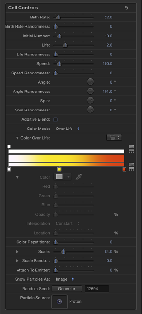
The following parameters apply to the creation and motion of the individual particles generated by each cell in an emitter. Cell controls appear at the bottom of the Emitter Inspector when a particle system is selected, and in the Particle Cell Inspector when a particle cell is selected.
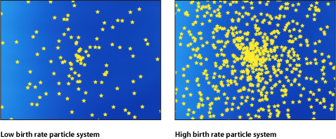
- Birth Rate Randomness: A slider that defines an amount of variance in the Birth Rate of generated particles. A value of 0 results in no variance—particles emerge from the emitter at the same rate. A value greater than 0 introduces a variance defined by the Birth Rate parameter, plus or minus a random value falling within the Birth Rate Randomness setting.
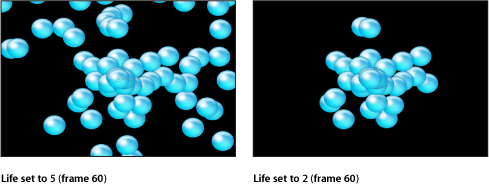
- Life: A slider that defines the duration of every particle, in seconds. This parameter specifies how long each particle lasts before vanishing from existence. This effect is similar to how sparks disappear after flying away from a sparkler. Unless the Color Over Life parameter or Opacity Over Life parameter is used to fade each particle out over its life, particles immediately vanish at the end of their lifetimes.
- Life Randomness: A slider that defines an amount of variance in the life of generated particles. A value of 0 results in no variance—all particles from the selected cell emerge with the same lifetime. A value greater than 0 introduces a variance defined by the Life parameter, plus or minus a random value falling within the Life Randomness setting.
- Speed: A slider that defines initial speed. This parameter determines how quickly each particle flies away from the emitter. This, in conjunction with the Life and Birth Rate parameters, determines how many particles appear in the Canvas at a given frame. It is equivalent to one of the functions of the graphical emission control in the HUD.
- Speed Randomness: A slider that defines an amount of variance in the speed of generated particles. A value of 0 results in no variance—all particles from the selected cell emerge with the same speed. A value greater than 0 introduces a variance defined by the Speed parameter, plus or minus a predetermined random value falling within the Speed Randomness setting.
- Align Angle: When this checkbox is selected, particles rotate to match the shape on which they are positioned. This parameter is available in all cases but the following: when the Shape setting (in the Emitter Inspector) is Rectangle, Circle, Image, Box, and Sphere and the Arrangement setting is with Tile Fill or Random Fill; or when the Shape setting is Point.
- Spin Randomness: A dial that defines an amount of variance in the spin of generated particles. A value of 0 results in no variance—all particles from the selected cell spin at the same rate. A value greater than 0 introduces a variance defined by the Spin parameter, plus or minus a random value falling within the Spin Randomness setting.
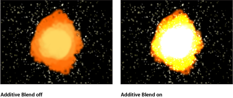
- Additive Blend: By default, particles are composited together using the Normal blend mode. Select this checkbox to composite all overlapping generated particles together using the Additive blending mode. This blending occurs in addition to whichever compositing method is already in use. The result is that the brightness of overlapping objects is intensified. This effect applies to the particle system itself—the blend mode of the emitter determines how the result of the emitter is blended into the scene.
- Color Mode: A pop-up menu that determines if and how particles are tinted. There are five options:
- Original: Particles are generated using their original colors. When Original is chosen, the Opacity Over Life parameter appears. Adjust the opacity controls to animate changes to the opacity of particles over their lifetime.
For more information on using the gradient controls, see Using the Gradient Editor.
- Colorize: Particles are tinted using the color specified in the Color parameter. When this setting is selected, additional Color and Opacity Over Life parameters appear.
- Color: Available when the Color Mode is set to Colorize, specifies a color to use to tint the particles. You can also modify the alpha channel of each particle, altering its opacity. This parameter is unique to the cell object. You can click the color well to choose a color, use the eye dropper, or open the disclosure triangle and adjust the Red, Green, Blue, and Opacity channel sliders.
For more information on using the Color controls, see Color Well.
For more information on using the gradient controls, see Using the Gradient Editor.
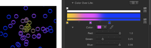
- Over Life: Particles are tinted based on their age, with the range of possible colors defined by the Color Over Life gradient editor.
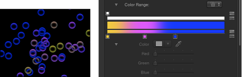
- Pick From Color Range: Particles are tinted at random, with the range of possible colors defined by the Color Range gradient editor. A point on the gradient is randomly chosen, so the relative sizes of each color region determine the frequency of the color being used.
For more information on using the gradient controls, see Using the Gradient Editor.
- Take Image Color: When you choose this menu item, each new particle’s color is based on the color of the image at the position where the particle was generated. This menu item is available only when the Shape pop-up menu in the Emitter Inspector is set to Image.
- Color Over Life: The Color Over Life gradient editor, available when the Color Mode is set to Over Life, defines the range of color that each particle assumes as it ages, beginning with the leftmost color in the gradient, and progressing through the range of colors until finally reaching the rightmost color at the end of its life. For more information on using the gradient controls, see Using the Gradient Editor.
- Color Range: This gradient editor appears when Color Mode is set to Pick From Color Range. Use it to define a range of colors used to randomly tint new particles. The direction of the gradient colors is not relevant, only the number of colors that appear in the gradient. The Color Range parameter has the same controls as the Color Over Life gradient editor.
- Scale: A slider that defines the scale of every particle of a cell. Click the disclosure triangle next to the Scale parameter to reveal separate X and Y scaling subparameters, which can be used to resize the width and height of generated particles. This control affects the initial scale of the particle (compared to the Scale Over Life behavior in the Particles behavior category).
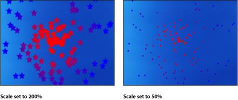
Note: When you use an image as a particle cell source and set a low Scale value, set the render quality in the Render pop-up menu (above the Canvas) or the View menu to Best (choose View > Quality > Best).
- Scale Randomness: A slider that defines an amount of variance in the scale of generated particles. A value of 0 results in no variance—all particles from the selected cell emerge with the same size. A value greater than 0 introduces a variance defined by the Scale parameter, plus or minus a random value falling within the Scale Randomness setting.
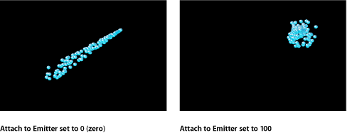
- Attach To Emitter: A slider that determines how closely particles follow the position of a moving emitter. If set to zero, particles follow their own path after being emitted, resulting in particles that trail along the motion path the emitter is following. If this parameter is set to 100, in the absence of other behaviors, all generated particles follow the emitter, surrounding it in a moving cloud of particles.
- Play Frames: This checkbox, which appears if the particle system was created from a QuickTime movie, controls playback. If selected, playback of the animation or movie clip used to generate each particle loops. If deselected, particles are generated using the still frame specified by the Random Start Frame parameter or the Source Start Frame parameter.
- Random Start Frame: This checkbox, which appears if the particle system was created from a QuickTime movie, introduces variation into animated particles generated from QuickTime objects. If selected, each newly generated particle begins at a different frame of the animation. Stills are chosen randomly if Play Frames is deselected.
- Source Start Frame: This slider is available if the particle system was created from a QuickTime movie, and Random Start Frame is deselected. Use it to set the start frame of the animation (if the Play Frames checkbox is selected) or the still frame to display (if the Play Frames checkbox is deselected).
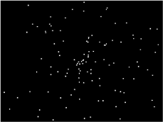
- Show Particles As: Use this pop-up menu to view particles in different preview modes, or as they actually appear. These nonimage modes play more efficiently when viewing a complex particle system and also provide other ways of analyzing particle motion. By default, this parameter is set to Image, which displays each particle as it is supposed to appear. There are four menu items:
- Points: Each particle is represented by a single point. This is the fastest preview mode and is useful for displaying the type and speed of particle motion in a system. When selected, the Point Size parameter is revealed.
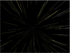
- Lines: Each particle is represented by a line. This is a good preview mode to use to analyze the vector of each particle’s motion. The length of each line is determined by that particle’s speed, and the angle of each line equals each particle’s direction.
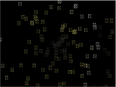
- Wireframe: Each particle is represented by a bounding box. Because the bounding boxes are good indicators of each particle’s orientation in the system, this preview mode is useful for evaluating the movements of individual particles. For example, it’s easy to see the angle of rotation for particles spinning or following a complex motion path.
- Image: Displays the full particle system effect.
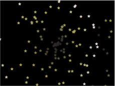
Note: Whatever is chosen in the Show Particles As pop-up menu appears in your final render. This can result in some interesting effects.
- Random Seed: Although particle systems seem random, they’re deterministic. This means that the variation in each particle system is created based on the number shown here. Unless this seed number is changed, a particle system with the same parameter settings always plays back with the same motion. If you don’t like the current random motion or distribution of the particle system, you can change the seed number by typing a new number or clicking Generate. This changes the random calculations performed for that system for all randomness parameters.
For more information about the random nature of particle systems, see The Predictability of Particle Systems.