Editing Shapes
After you draw a shape using the Bezier or B-Spline shape tools, you can adjust the fill, outline, and feathering to suit your needs.
Note: You can only feather shapes that have the outline turned off.
Select a shape, then open the Shape Inspector.
To manipulate the shape’s outline, do any of the following in the Style pane of the Shape Inspector:
To turn a shape’s outline on or off, click the Outline checkbox. When selected, the checkbox turns blue.
To change the color of the outline, use the Brush Color parameter in the Outline controls.
To change the width of the outline, drag the Width slider.
Note: You can also use the Shape HUD to turn the outline on and off, and to change its color, roundness, and width.
To change how the outline’s sharp corners are drawn, choose an item from the Joint pop-up menu.
To change the shape of an outline’s start and end caps, choose an item from the Start Cap or End Cap pop-up menu.
To change whether the outline appears over or under a shape’s fill, choose a command from the Order pop-up menu.
To change the outline from the default solid to an editable paint stroke, set Brush Type to Airbrush or Image. For more information, see Style Pane Controls in the Inspector.
To change the roundness of the outline, adjust the Roundness slider in the Geometry pane of the Shape Inspector (or in the Shape HUD).
Choose the Bezier or B-Spline shape tool (press B).
Create the necessary control points for the shape you need.
For more information, see Shape and Mask Drawing Tools.
When you’re ready to close the shape, click the first point you created.
By default, new closed shapes are filled. To make the shape empty, select it, then deselect the Fill checkbox in the Style pane of the Shape Inspector (or in the Shape HUD).

Select a shape, then open the Shape Inspector.
In the Style pane of the Shape Inspector, do any of the following:
To turn a shape’s fill on or off, click the Fill checkbox.
To change a shape’s fill mode from a solid color to a gradient, choose an item from the Fill Mode pop-up menu.
If the shape’s fill mode is set to a solid color, you can choose the color using the Fill Color controls.
If the shape’s fill mode is set to a gradient, you can choose a gradient from the gradient preset pop-up menu, or click the Gradient parameter’s disclosure triangle to display the gradient editor and create your own custom gradient. For more information on using gradient editors, see Gradient Controls.
Select the shape to feather.
If the shape’s outline is visible, deselect the Outline checkbox in the Style pane of the Shape Inspector.
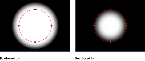
Adjust the Feather slider in the HUD or in the Style pane of the Shape Inspector.
Positive values spread the feathering outward, while negative values feather the shape inward.
Optionally, you can also adjust the Falloff parameter in the Style pane of the Shape inspector, which controls how steep the feathering is.
Tip: You can also blur a shape using filters. For more information, see Applying Filters to Shapes.
Creating Rectangles, Circles, and Lines
The Rectangle and Line tools create simple linear shapes. The Circle tool creates a simple Bezier shape. After a shape is drawn, it can be converted to a Linear, Bezier, or B-Spline shape in the Inspector. The resulting shapes can be edited like any other Bezier shape, using the methods described in How to Edit Shapes.
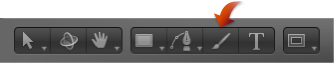
Select the Rectangle tool in the toolbar (or press R).
The Rectangle Tool HUD appears. To change the color or roundness of the shape before it is drawn, use the controls in the HUD. Select the Outline checkbox to create an outline with the shape. The Width slider adjusts the width of the outline.
The Rectangle shape layer does not appear in the Layers list until the shape is drawn.
Note: Outlines can be added and edited after a shape is drawn.
Click in the Canvas to define the first corner of the rectangle, drag until the resulting rectangle is the size you want, then release the mouse button to finish drawing.
Note: To create a perfect square, press Shift while you drag. To draw the rectangle from its center, press Option while you drag.
After you create the shape, press Esc to exit shape-drawing mode and activate the Select/Transform tool.
The Shape HUD appears.
Create a rectangle shape as described above.
Do one of the following:
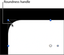
Drag the roundness handle in the upper left corner of the shape.
In the HUD, adjust the Roundness slider.
Note: You can also set the Roundness value in the Shape HUD before drawing the rectangle.
In the Inspector, open the Geometry pane and adjust the Roundness slider.
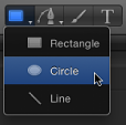
Choose the Circle tool from the shape tools pop-up menu in the toolbar (or press C).
The Circle Tool HUD appears. To change the color of the shape before it is drawn, use the color controls in the HUD. Select the Outline checkbox to create an outline with the shape. The Width slider adjusts the width of the outline.
Click in the Canvas to define the start point of the bounding box that defines the circle, drag until the resulting circle is the size you want, then release the mouse button to finish drawing.
Note: To create a perfectly symmetrical circle, press Shift while you drag. To draw the circle from its center, press Option while you drag.
Tip: If you change a circle’s Shape Type to B-Spline in the Geometry pane of the Shape Inspector, you can use different methods to manipulate the circle.
After you create the shape, press Esc to activate the Select/Transform tool.
The Shape HUD appears.
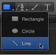
Choose the Line tool from the shape tools pop-up menu in the toolbar.
The Line Tool HUD appears. To adjust the color and width of the line before it is drawn, use the controls in the HUD.
Click in the Canvas to define the start point of the line, and keep holding down the mouse button.
Drag until the resulting line is the length you want, then release the mouse button.
Tip: Pressing Shift while dragging constrains the line movement to 45-degree angles.
Important: Because a line is really an outline, all Outline parameters in the Inspector apply to a line.
After you create the shape, press Esc to activate the Select/Transform tool.
The Shape HUD appears.
Note: Rectangles and circles can be converted into paint strokes by selecting the shape’s Outline checkbox and choosing a different brush type in the Inspector. For more information, see Using a Shape Outline as a Paint Stroke.
Creating Paint Strokes
Unlike a freehand Bezier or B-Spline shape drawn one point at a time, a paint stroke is typically created with one continuous movement.
Technically, paint strokes are outline-only shapes created using any shape tool. An outline-only shape is indicated by a paintbrush icon in the Layers list and Timeline. This icon changes to a shape icon when a shape fill is enabled.
Note: The Paint Stroke feature is a design and graphics tool, not a retouching or rotoscoping tool.
There are two ways to create a paint stroke:
Select the Paint Stroke tool in the toolbar, then draw a stroke in the Canvas using a stylus and tablet (or a mouse).
Create a shape (paint stroke, line, rectangle, or circle) in the Canvas, select the Outline checkbox in the Style pane of the Shape Inspector, then choose Airbrush or Image from the Brush Type pop-up menu.
For more information about converting a shape to an editable paint stroke, see Using a Shape Outline as a Paint Stroke.
The Paint Stroke tool creates a shape outline comprised of dabs. Dabs—analogous to the cells of a replicator or particle emitter—define the appearance of the stroke. Although particle cells can emit various particle types, airbrush paint strokes have only a single dab type. The dabs can be very close together or spaced widely apart along the stroke. The dabs’ color, opacity, spacing, scale, angle, and so on can be modified in the Inspector after a stroke is created.
For more information on modifying a paint stroke after the stroke is created, see Stroke Pane Controls in the Inspector.
Paint strokes can be animated using behaviors or by keyframing. In addition to Basic Motion, Simulation, and Parameter behaviors, shapes have their own category of behaviors that includes a behavior to sequence effects over the length of the stroke. For more information on using the Shape behaviors, see Shape Behaviors.
Note: The stroke’s shape (defined by its control points) and open/closed state can be modified in the Canvas or Inspector. Because a stroke is a shape, it can be edited like any other shape, using the methods described in How to Edit Shapes.
After you select the Paint Stroke tool in the toolbar and before drawing the stroke in the Canvas, you can define the color and other attributes of the stroke in the Paint Stroke Tool HUD. In the HUD, you select a preset shape style to use as your brush source.
There are several ways to set the style of a paint stroke:
Select a preset shape style in the Paint Stroke Tool HUD before drawing a stroke. If no preset shape is selected before drawing a stroke, a basic solid stroke (outline) is created.
Modify a paint stroke created with the Paint Stroke tool using the Shape Style pop-up menu in the Style pane of the Shape Inspector.
Select the Outline checkbox in the Shape HUD or the Style pane of the Shape Inspector, then modify the outline of a shape (circle, rectangle, and so on) using the Outline parameter controls.
Drag a shape style (in the Shape Styles category) from the Library to the paint stroke layer in the Layers list. The style of the shape from the Library is applied to the paint stroke.
Depending on the effect you want, you may achieve better results using a stylus and tablet with the Paint Stroke tool. Many styles and brushes take advantage of the pen pressure and speed applied when creating the stroke using a graphics tablet. You can apply the pressure or speed to different stroke parameters, such as width, opacity, and spacing. For example, choosing Width from the Pen Pressure pop-up menu in the Paint Stroke Tool HUD results in wider strokes when you apply more pen pressure.
Using the Write On parameter, you can record a stroke so it “draws” over time. In this case, a Write On Shape behavior is applied to the stroke using as its settings the time it took to draw the stroke and the speed at which each section of the stroke was created. These settings can be modified after the stroke is created. A Write On behavior can also be applied after a paint stroke is created. For more information on using the Write On behavior, see Write On.
Select the Paint Stroke tool (or press P).
The Paint Stroke tool HUD appears. (If it doesn’t appear, press F7.)
Important: Like the other drawing tool HUDs, the Paint Stroke Tool HUD is available only after the Paint Stroke tool is selected and before you create your stroke in the Canvas. The Paint Stroke Tool HUD allows you to determine the properties derived from the pressure and speed of the stylus before the stroke is drawn.
Define a paint stroke style in the HUD:
Choose an option from the Shape Style preset pop-up menu.
Modify the Brush Color and Width settings.
If a preset is not used, a basic solid stroke is created. You can still apply a preset to the stroke using the Inspector. Presets do not override the width or color of the stroke set in the HUD.
Note: The Pen Pressure and Pen Speed parameters become available depending upon the chosen style. These parameters are not available with a solid brush type.
If you want to create a stroke that is drawn over time, select the Write On checkbox.
When a paint stroke is created with the Write On checkbox selected, a Write On behavior is applied to the stroke. As with any other behavior, you can modify its parameters in the HUD or Inspector. For more information on using the Write On behavior, see Write On.
Draw your stroke in the Canvas, then press S or Esc to activate the Select/Transform tool.
The Paint Stroke Tool HUD is replaced with the Shape HUD, which contains basic parameters identical to all other shape HUDs. Consequently, after a stroke is drawn, you must use the Inspector to modify parameters unique to the paint stroke and its dabs.
The lower portion of the Paint Stroke Tool HUD contains a sketch area that allows you to preview a paint stroke effect.
Select the Paint Stroke tool in the toolbar.
Do one of the following:
Select any brush style in the Paint Stroke Tool HUD, then draw a stroke in the sketch area to see a preview of the paint stroke.
Select the Write On checkbox, draw a stroke in the sketch area, then click the Play button to see a preview of the write-on stroke.
Apply a preset from the Shape Style pop-up menu to an existing stroke in the sketch area.
If the preset is an animated stroke, the stroke is automatically drawn in the sketch area. Press the Play button to see the stroke animation again.
Note: To create a paint stroke that is “painted” on the Canvas over time (if your chosen preset is not animated), select the Write On checkbox in the HUD before drawing the paint stroke in the Canvas.
Important: Some operations, as well as the application of some filters or a mask, cause a group to be rasterized. Because all paint strokes live in groups, this affects how strokes interact with other objects in your project. For more information, see Groups and Rasterization.
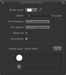
Paint Stroke Tool HUD Parameters
The Paint Stroke Tool HUD appears after the Paint Stroke tool is selected in the toolbar and before a stroke is drawn. This HUD contains controls that define the color and width of the stroke and how pen pressure and speed affect the stroke (opacity, width, and so on), a checkbox that allows the stroke to be “drawn in” over time, smoothing controls, and a Shape Style pop-up menu for quick access to preset brush styles and a sketch area for sampling these brush styles.
- Brush Color: A color well and eyedropper that set the color of the brush. For more information on using these controls, see Color Controls.
- Pen Pressure: When creating paint strokes, this pop-up menu allows you to determine stroke properties derived from the pressure of your pen before creating the stroke. This parameter is not available for solid brush types. Choose from one of the following:
Note: Only strokes drawn using a stylus and tablet will have recorded pressure variations.
- Nothing: Pen pressure is ignored.
- Width: The harder the pen pressure, the wider the stroke. To adjust the width of the dabs after the stroke is created, use the width and brush scale controls in the Style and Stroke panes.
- Opacity: The harder the pen pressure, the more opaque the stroke. To adjust the opacity of the dabs after the stroke is created, use the opacity controls in the Style or Stroke pane.
- Spacing: The harder the pen pressure, the greater the spacing between stroke dabs. To adjust the spacing of the dabs after the stroke is created, use the spacing controls in the Style or Stroke pane.
- Angle: The harder the pen pressure, the greater the angle of the stroke dabs. To adjust the angle of the dabs after the stroke is created, use the angle controls in the Stroke pane.
- Jitter: The harder the pen pressure, the larger the amount of jitter on the stroke. Jitter randomizes the position of the paint dabs, giving the dabs a particle-like appearance. To adjust the jitter of the dabs after the stroke is created, use the jitter controls in the Stroke pane.
Note: You can affect multiple parameters on a single stroke, such as pressure affecting opacity and spacing. Choose an option, such as Opacity, before the stroke is created. After you create the stroke, apply a pen shape behavior to the stroke and apply the action to another parameter, such as Spacing. For more information on the pen shape behaviors, see Shape Behaviors.
- Pen Speed: This pop-up menu allows you to affect the stroke’s width, opacity, spacing, angle, and jitter based on the speed recorded when drawing the stroke with the paint stroke tool. These settings can be applied to paint strokes created using a stylus and graphics tablet or mouse. This parameter is not available for solid brush types. Choose from one of the following:
- Nothing: Pen speed is ignored.
- Width: The faster you move the pen, the more narrow the stroke; the slower you move the pen, the wider the stroke. To adjust the width of the dabs after the stroke is created, use the width and brush scale controls in the Style and Stroke panes.
- Opacity: The faster you move the pen, the less opaque the stroke. To adjust the opacity of the dabs after the stroke is created, use the opacity controls in the Style or Stroke pane.
- Spacing: The faster you move the pen, the greater the spacing between the dabs of the stroke. To adjust the spacing of the dabs after the stroke is created, use the spacing controls in the Style or Stroke pane.
- Angle: The faster you move the pen, the greater the angle of the stroke dabs. To adjust the angle of the dabs after the stroke is created, use the angle controls in the Stroke pane.
- Jitter: The faster you move the pen, the larger the amount of jitter on the stroke. Jitter randomizes the position of the paint dabs so they appear more like particles. To adjust the jitter of the dabs after the stroke is created, use the jitter controls in the Stroke pane.
- Write On: This checkbox, when selected, allows a stroke to be “painted” on the Canvas over time. For more information, see Write On.
Shapes as a Layer
After you create a shape (including paint strokes), it becomes a layer. Because shape layers share most of the characteristics of other layers in Motion, you can use the transform tools—Select/Transform, Anchor Point, Drop Shadow, Distort, and Crop—to transform a selected shape layer. These onscreen tools are shortcuts to the controls in the Properties Inspector. To set specific values, or fine-tune any of the transforms, use the Properties Inspector.
For more information on the Properties Inspector and onscreen transform tools, see Parameters in the Properties Inspector.
Important: Some operations, as well the application of some filters or a mask, cause a group to be rasterized. When a group is rasterized, it is converted into a bitmap image. Because all shape (masks, shapes, and paint strokes) layers live in groups, this affects how shapes interact with other objects in your project. For more information, see Shapes and Rasterization.
How to Edit Shapes
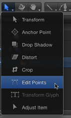
There are two ways to edit shapes. You can edit them in their entirety, like any other object, using the 2D transform tools, or you can adjust them point by point using the Edit Points tool.
You perform most of your detailed editing using a shape’s individual control points. The Select/Transform tool is better for overall transformations of an entire shape. The following guidelines apply to all shape types: shapes, masks, and paint strokes.
Using Dynamic Guides and Snapping While Editing
The Canvas dynamic guides and control point snapping help you connect selected points to themselves, or to other objects.
In the View pop-up menu above the right side of the Canvas, ensure that the Dynamic Guides item is checkmarked.
In the menu bar, choose View > Snap to ensure that snapping is turned on.
When active, a check mark appears next to the menu item.
Select the shape to edit, then choose the Edit Points tool from the 2D transform tools pop-up menu in the toolbar.
Note: In the Canvas, you can also Control-click a shape and choose Edit Points from the shortcut menu.
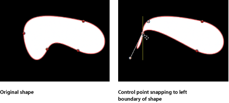
In the Canvas, drag a control point.
Yellow guides appear when the selected control point aligns with itself or with the edges or center of other objects.
In the View pop-up menu above the right side of the Canvas, ensure that the Dynamic Guides item is checkmarked.
Choose View > Snap to ensure snapping is turned on.
When active, a check mark appears next to the menu item.
Select the shape to edit, then choose the Edit Points tool from the 2D tools pop-up menu in the toolbar.
Note: In the Canvas, you can also double-click a shape or Control-click a shape and choose Edit Points from the shortcut menu to show its control points.
Shift-click to select another shape.
In the Canvas, drag a control point on the originally selected shape.
Guides appear when the selected control point aligns with other control points on the shape being edited, as well as with other shapes in the Canvas.
Yellow guides appear when the selected control point aligns with itself or with the edges or center of other objects.
Use the following guidelines to turn off snapping, to allow for subtle shape adjustments:
Press N to turn off snapping. Press N again to turn snapping back on.
As you begin to move the selected control point, press and hold the Command key to turn off snapping as you drag the point.
Note: If you press Command and then drag a control point, adjustable tangent handles are created. If you press Command and click a curved point, that point becomes a corner point. For more information on editing Bezier curve control points, see Editing Bezier Control Points.
Click the Select/Transform tool.
Click a shape in the Canvas.
Move, resize, or rotate the shape.
Note: To enter control point-adjustment mode in the Canvas, double-click the shape.
When you move, resize, or rotate, a shape, you also transform its control points to match the new orientation of the shape.
For more information about how to perform object transformations, see 2D Transform Tools.
Displaying a Shape’s Control Points
There are several ways to display the control points of a shape to allow point-by-point editing in the Canvas.
Select the shape to edit, then choose the Edit Points tool from the 2D tools pop-up menu in the toolbar.
The control points appear.
Choose the Edit Points tool from the 2D tools pop-up menu in the toolbar, then select a shape in the Layers list or Timeline.
Double-click a shape.
Control-click a shape in the Canvas, then choose Edit Points from the shortcut menu.
Note: Overlays must be enabled in the View pull-down menu (or the View pop-up menu) to see the control points and spline of a shape. In addition, if Handles are turned off in the View > Overlays submenu (or the View pop-up menu), you cannot see a shape’s Bezier or B-Spline control points when editing. When editing shapes, make sure that Handles are enabled (in the View pull-down menu or View pop-up menu).
After you display a shape’s control points, select control points to edit them.
While editing the control points of a shape, you can select another shape and remain in control point-adjustment mode. This allows for quick modification of multiple shapes’ control points.
Selecting and Deselecting Control Points on a Shape
The following tasks describe how to select and deselect control points in the Canvas. For all these procedures, use the Edit Points tool (in the 2D tools pop-up menu).
Click any control point.
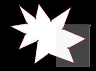
Drag a selection box over multiple points.
Shift-click unselected control points to add them to the selection.
Shift-drag a selection box around unselected control points to add them to the selection.
Note: In Edit Points mode, when you place the pointer over a control point, an info window appears identifying the control point name. When dragging a control point, the info window displays the point’s name and coordinates. You can choose not to display this info by opening the General pane of the Motion Preferences window and deselecting Show Tooltips.
With the shape selected in the Canvas, choose Edit > Select All (or press Command-A).
Shift-click selected points.
Shift-drag a selection box over selected points.
Click the Canvas anywhere outside the selected shape.
Choose Edit > Deselect All (or press Command-Shift-A).
Enable Show Tool Info in the View pop-up menu, then position the pointer over any control point to display its control point number.
Note: All shape control points are also listed by number in the Geometry pane of the Shape Inspector.
Moving Control Points to Adjust a Shape
Because control points define the shape, you can move control points to change the shape. For all procedures described below, use the Edit Points tool (in the 2D tools pop-up menu).
Tip: You can also modify multiple control points across different shapes simultaneously by selecting them all at once.
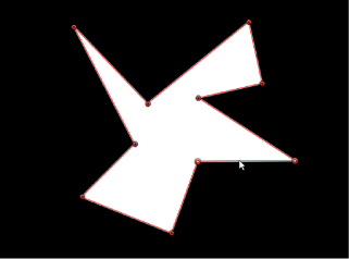
Select control points on the shape in the Canvas, then drag the points to a new position.
As you drag selected control points, the rest of the shape stretches or curves to accommodate the change.
Press Command-Left Arrow, Command-Right-Arrow, Command-Up Arrow or Command-Down Arrow to nudge a point by one pixel (or Command-Shift to nudge by 10 pixels).
Select control points.
Press Shift while you drag a selected point horizontally, vertically, or diagonally.
Important: Selected control points can only be moved—you cannot corner-pin them. To rotate or scale them, you must use the Transform Control Points command. See Transforming Multiple Control Points.
Modifying Shape Edges
You can also select the line between two points and move the edge of the shape without affecting the rest of the shape.
With the Edit Points tool active, click any edge of a shape object.
The control points on either side of the line are selected.
Drag the line segment.
The distance between the two points remains constant, but the line can be moved freely. Press Shift to constrain the movement horizontally, vertically, or diagonally.
To release the selection, click anywhere outside the selection, or choose a different tool in the toolbar.
Transforming Multiple Control Points
You can scale and rotate a group of points as if they were a single object by using the Transform Control Points command. The lines connecting the selected points to unselected points will move and adjust.
With the Edit Points tool selected, drag a selection box around the points you want to modify.
Choose Edit > Transform Control Points or press Command-Shift-T.
A transform box appears around the selected points.
Note: Transform Control Points is only available when at least two points on the same spline are selected.
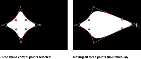
Scale, rotate, offset the anchor point, and reposition the group of points as if they were a single object.
Click anywhere outside the selection, or switch to a different tool to release the selection.
Adding and Deleting Control Points
If you did not create enough control points to make the shape you need, you can add more to the existing shape. You can also extend or close an open shape.
Choose the Edit Points tool.
Do one of the following:
Option-click or double-click the edge of a shape to add a new control point.
Note: To add control points to a B-Spline shape, Option-click or double-click the B-Spline frame’s edge, rather than the edge of the shape itself.
Control-click the edge of a shape, then choose Add Point from the shortcut menu.
Adding more control points does not immediately change a Bezier shape, unless you drag Bezier curve points as you create them.
However, adding more control points to a B-Spline shape usually changes its shape.
Select an open shape with the Edit Points tool.
Option-click anywhere outside the shape to add control points to the end of the shape.
Click the first point in the shape to close it (or place the pointer over the first point and press C).
The closed shape is not filled.
With the Edit Points tool active, click the first point in the shape to close it (or press C).
The closed shape is not filled.
Control-click a control point, then choose Close Curve from the shortcut menu.
Display the Geometry pane in the Shape Inspector, then select the Closed checkbox.
You can reopen the shape by deselecting the Closed checkbox.
Control-click a point on the shape, then choose Open Curve from the shortcut menu.
The segment before the point (in a clockwise order) is removed from the shape. This action causes the selected point to become Control Point 1 and the remaining points to be renamed accordingly. If the originally closed shape was filled, the Fill checkbox remains selected. To disable the fill, deselect the Fill checkbox in the HUD or Style pane of the Shape Inspector.
Select the shape and deselect the Closed checkbox in the Geometry pane of the Shape Inspector.
Note: The spline before the first point drawn is removed. To change the start point (the first point drawn) of the shape, Control-click a point and choose Set Start Point from the shortcut menu.
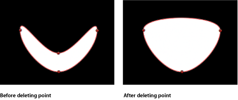
If a shape has more control points than are necessary, you can delete points from it to make it easier to edit. This can be helpful if you animate the shape later on.
Select a shape with the Edit Points tool.
Select points to delete, then do one of the following:
Choose Edit > Delete.
Control-click the selected points, then choose Delete Point from the shortcut menu.
Press Delete.
The shape changes to adjust to the missing point. If you remove points from a closed shape, the shape remains closed.
Warning: If you delete a point from a shape that has a keyframed shape animation parameter in the Keyframe Editor, that control point is removed from the entire animation.
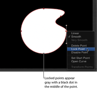
Locking Control Points
You can lock control points in a shape to fix them in place and prevent accidental modification. A shape with locked points can still be moved.
Choose the Edit Points tool, then select a shape.
Control-click a control point, then choose Lock Point from the shortcut menu.
If the point was unlocked, it becomes locked. If the point was locked, Unlock Point appears in the shortcut menu, and the point becomes unlocked.
Editing Bezier Control Points
The methods used to adjust Bezier shapes are similar to those used by many other applications. Bezier control points are widely used to modify curves, and allow you to easily draw any shape you may need.
Each point in a Bezier shape can be converted from a hard corner to a curve.
Note: For all procedures described below, use the Edit Points tool (in the 2D tools pop-up menu).
Command-click a curved point to turn it into a corner (Linear) point.
Command-drag a corner point to turn it into a curved (Bezier) point, creating adjustable tangent handles.
Control-click selected points, then choose Linear, Smooth, or Very Smooth (for B-Splines) from the shortcut menu to change the control point type.
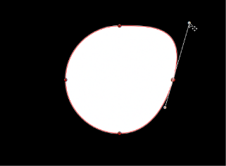
Curved Bezier control points have two tangent handles that you use to adjust the curvature of the shape on either side of the control point. These handles can be adjusted in various ways to create symmetrical and asymmetrical curves. By default, these tangent handles are locked to one another at an angle of 180 degrees, although this can be overridden to allow each tangent to be independently adjusted.
Important: If Record (automatic keyframing) is turned on, turning a corner into a curve causes an animated effect in which the corner gradually turns into the curve.
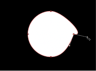
Drag a tangent handle to adjust its length. By default, the opposing tangent is locked to 180 degrees, and adjusting the angle of one tangent adjusts the other. However, the length of each tangent can be independently adjusted.
Option-drag either tangent to break the relationship between opposing tangents. After this relationship is broken, adjustments to one tangent have no effect on the other, and both tangents can be rotated freely.
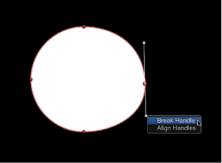
Control-click a handle control point, then choose Break Handle from the shortcut menu to break the relationship between opposing handles.
Option-drag a broken tangent or Control-click a handle control point and choose Link Handle from the shortcut menu to lock the angle of the tangents together again. The tangents now maintain their relationship when moved and rotated.
Note: You can also press Command-Option and drag a control point so the tangents maintain their broken relationship when moved and rotated.
Control-click a handle control point and choose Align Handles from the shortcut menu to align the tangents to a 180-degree angle.
Tip: Press Shift while you adjust a tangent to constrain its movement to 45-degree angles.
To simultaneously modify the handles for more than one control point, Shift-select the points (on the same spline) and then adjust the tangents.
Important: If Record (automatic keyframing) is enabled, curve adjustments are keyframed, creating animated shape changes. Additionally, if a keyframe has been added to the Control Points parameter in the Geometry pane of the Shape Inspector, curve adjustments are keyframed, regardless of the Record button state.
Editing B-Spline Control Points
Editing the position of control points in B-Spline shapes is similar to editing Bezier shapes. In fact, the steps for selecting, moving, adding, deleting, and locking control points are almost exactly the same. The main difference in editing both types of shapes lies in how you manipulate and adjust curves.
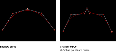
The simplest, and usually fastest, way to manipulate B-Spline curves is to move B-Spline points closer to or farther from one another. When B-Spline points are moved closer to one another, a sharper curve is created. B-Spline points that are farther from one another create shallower curves.
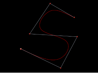
Each B-Spline control point tugs on a section of the shape, pulling it toward itself. As a result, you manipulate a shape’s curve by moving its control points in the direction you want to pull the shape. For example, notice how every control point creating the S curve below is offset in the direction of the curve it influences.
Note: You can show and hide the B-Spline frame lines that enclose B-Spline control points by choosing View > Overlays > Lines.
By default, B-Spline shapes have no corners. Although this is the default behavior, you can adjust the amount of curvature at each B-Spline control point. This allows you to create sharper curves using fewer control points, even creating corners at a single point, if necessary.
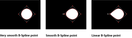
The easiest way to adjust B-Spline point curvature is by Command-dragging the control point. You can also switch among three preset degrees of curvature.
Command-drag selected B-Spline control points to make their curves progressively sharper. A handle appears indicating the curvature adjustment you’re making.
Dragging away from the point makes the curve progressively sharper.
Dragging toward the point makes the curve progressively looser.
Note: After the handle appears, you can modify the curve without the Command key. Drag the handle away from the point to make the curve sharper. Drag the handle toward the point to make the curve looser.
After creating handle by Command-dragging a B-Spline point, Command-click the handle to switch between three progressively sharper amounts of curvature.
Control-click a B-Spline point, then choose Very Smooth, Smooth, or Linear from the shortcut menu.
Using a Shape Outline as a Paint Stroke
You can convert a shape outline into a paint stroke by modifying the Brush Type in the Inspector. After a shape outline is assigned a different brush type, paint stroke parameters become available. You can modify and animate its brush parameters, as well as apply the Sequence Paint behavior.
Select an existing shape.
In the Shape HUD or Style pane of the Shape Inspector, select the Outline checkbox.
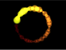
Modify any Outline parameter you want. In this example, the outline is widened and colored orange.

If you don’t want the shape filled, deselect the Fill checkbox in the Shape HUD or Style pane of the Shape Inspector.
Note: Solid must be chosen from the Brush Type pop-up menu in the Style pane of the Shape Inspector for the shape fill options to remain available.

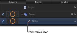
After Fill is deselected, the shape icon in the Layers list becomes a paint stroke icon.
In the Style pane of the Shape Inspector, choose Airbrush from the Brush Type pop-up menu.
After the Brush Type is changed to Airbrush (or Image), the following occurs:
The stroke softens because it is using a soft brush type. A paint stroke is comprised of dabs and the brush type is the source for the dabs. The brush profile can be modified to vary opacity within the brush. You can apply a custom opacity gradient to the brush profile.
The Stroke pane becomes available. Use the Stroke pane to set the Stroke Color mode and Brush Scale parameters, and to adjust various options.
The Advanced pane becomes available. The Advanced pane contains a single group of Dynamics controls that allow the dabs of a paint stroke to be animated like particles. For more information on Dynamics, see Advanced Pane Controls In the Inspector.
Note: When a paint stroke is created using the Paint Stroke tool in the toolbar, additional stylus parameters appear in the Advanced pane.
Use the controls in the Style, Stroke, and Advanced panes of the Shape Inspector to modify or animate your paint stroke.
For a complete description of these parameters, see Style Pane Controls in the Inspector, Stroke Pane Controls in the Inspector, and Advanced Pane Controls In the Inspector. In the example below, the Additive Blend parameter is enabled in the Style pane. Additionally, the Color Over Stroke, Spacing Over Stroke, Width Over Stroke, Brush Scale, and Brush Scale Randomness parameters are modified in the Stroke pane.