Shape Behaviors
Shape behaviors are specifically designed to be applied to shapes created in Motion. After drawing a stroke or other shape, apply a Shape behavior to wriggle, oscillate, or randomize a shape’s control points or to map pen pressure to various paint stroke characteristics.
Apply Pen Pressure
This behavior is designed to be applied to a paint stroke created using a stylus and graphics tablet. After you create a stroke, this behavior allows you to affect the width, opacity, spacing, angle, or jitter of the paint stroke based on the pressure of your stylus on the tablet when the stroke was created.
Note: These parameters are identical to the Pen Pressure parameters in the Advanced pane of the inspector. You can choose to use the Advanced pane parameters or this shape behavior to apply the pressure data to the paint stroke. You can use a combination of Pen Pressure parameters in the Advanced pane and Apply Pen Pressure shape behaviors to affect more than one parameter (such as Opacity, Width, or Jitter) of the stroke using the same pressure data.
- Apply To: Use this pop-up menu to select how your paint stroke is affected by pen pressure. There are five options:
- Width: Pen pressure affects the width of the stroke. The harder the pressure, the wider the stroke.
- Opacity: Pen pressure affects the opacity of the stroke. The harder the pressure, the more opaque the stroke.
- Spacing: The harder the pressure, the greater the spacing between stroke dabs.
- Angle: The harder the pressure, the greater the angle of the stroke dabs.
- Jitter: The harder the pressure, the larger the amount of jitter on the stroke. Jitter randomizes the position of the paint dabs so they appear more like particles.
- Min Pressure: Adjusts the minimum threshold of pressure sensitivity. Pressure values below the minimum value are remapped to 0. For Opacity and Width, those remapped values do not appear. For Spacing, Angle, and Jitter, the values are not modified. If the Min and Max pressure are plotted on a graph, Min Pressure represents the minimum value, or 0. The area of the graph between Min and Max is remapped to the output values.
- Max Pressure: Adjusts the maximum threshold of pressure sensitivity. Pressure values above the maximum value are remapped to 1. For Opacity, Width, Spacing, Angle, and Jitter, those values will have the greatest effect. If the Min and Max pressures are plotted on a graph, Max Pressure represents the maximum value, or 1. The area of the graph between Min and Max is remapped to the output values.
- Scale: Determines the magnitude of the effect. Defines the output range for the dabs based on the mapped values between minimum (0) and maximum (1) pressure, multiplied by the value defined in the slider (or value field). This amount is then applied to the parameter (width, opacity, and so on) by multiplying (for width, opacity, spacing, and jitter) or adding (for angle). This control is independent of the Scale parameter in the Stroke pane.
The parameters in the HUD are identical to the parameters in the Inspector.
Apply Pen Speed
When using a stylus or mouse to create paint strokes, this behavior allows you to affect the width, opacity, spacing, angle, or jitter of the paint stroke based on the speed of your pen strokes.
Note: A paint stroke created by using a mouse can be affected by the Apply Pen Speed behavior.
The parameters in the HUD are identical to the parameters in the Inspector.
Note: In the Paint Stroke Tool HUD, you can select how the speed of the stylus affects the stroke before the stroke is created. Applying the Pen Speed behavior allows you to affect more than one parameter (such as Opacity, Width, or Jitter) of the stroke using the same pressure data. The Pen Speed parameter also appears in the Advanced pane of the Shape Inspector.
- Apply To: Use this pop-up menu to select how your paint stroke is affected by pen speed. There are five options:
- Width: The quicker you move the pen, the more narrow the stroke; the slower you move the pen, the wider the stroke.
- Opacity: Pen speed affects the opacity of the stroke. The faster you move the pen, the less opaque the stroke.
- Spacing: The faster you move the pen, the greater the spacing between stroke dabs.
- Angle: The faster the movement of the pen, the greater the angle of the stroke dabs.
- Jitter: The faster the movement of the pen, the larger the amount of jitter on the stroke. Jitter randomizes the position of the paint dabs so they appear more like particles.
- Min Speed: Adjusts the minimum threshold of speed sensitivity. Speed values below the minimum value are remapped to 0. For Opacity and Width, those values do not appear. For Spacing, Angle, and Jitter, the values are not modified. If the Min and Max speeds are plotted on a graph, Min Speed represents the minimum value, or 0. The area of the graph between Min and Max is remapped to the output values.
- Max Speed: Adjusts the maximum threshold of speed sensitivity. Speed values above the maximum value are remapped to 1. For Opacity, Width, Spacing, Angle, and Jitter, those values will have the greatest effect. If the Min and Max speeds are plotted on a graph, Max Speed represents the maximum value, or 1. The area of the graph between Min and Max is remapped to the output values.
- Scale: Determines the magnitude of the effect. Defines the output range for the dabs based on the mapped values between minimum (0) and maximum (1) speed, multiplied by the value defined in the slider (or value field). This amount is then applied to the channel (width, opacity, and so on) by multiplying (for width, opacity, spacing, and jitter) or adding (for angle). This control is independent of the Scale parameter in the Stroke pane.
The parameters in the HUD are identical to the parameters in the Inspector.
Apply Pen Tilt
When you use a stylus to create paint strokes using the paint stroke tool, this behavior allows you to affect the width, opacity, spacing, angle, or jitter of the paint stroke based on the tilt of the pen while creating strokes.
Note: You can use a combination of Apply Pen Tilt shape behaviors to affect more than one parameter (such as Opacity, Width, or Jitter) of the stroke using the same tilt data.
- Apply To: Use this pop-up menu to select how your paint stroke is affected by the tilt of your pen as you draw. There are five options:
- Width: The tilt of the stylus affects the width of the stroke. The greater the tilt, the wider the stroke.
- Opacity: The tilt of the stylus affects the opacity of the stroke. The greater the tilt, the more opaque the stroke.
- Spacing: The greater the tilt of the stylus, the greater the spacing between stroke dabs.
- Angle: The greater the tilt of the stylus, the larger the value of the angle of the stroke.
- Jitter: The greater the tilt of the stylus, the larger the amount of jitter on the stroke. Jitter randomizes the position of the paint dabs so they appear more like particles.
- Calculate Tilt: The pen tilt is measured on two axes: X and Y. X represents the stylus tilting to the right and left (toward the right or left side of the tablet); Y represents the stylus tilting up and down (toward the top or bottom of the tablet). Use this pop-up menu to select how the tilt of the stylus affects the stroke. There are five options:
- Absolute: Takes the maximum tilt from any axis.
- X Only: Measures the tilt only on the X axis.
- Y Only: Measures the tilt only on the Y axis.
- Axis: When Axis is chosen from the Calculate Tilt pop-up menu, the Tilt Axis parameter becomes available.
- Polar: Uses the tilt of the stylus as if it were an angle. When viewed from above, the stylus points in a specific direction. That angle represents a polar value.
- Min Tilt: Adjusts the minimum threshold of tilt sensitivity. Tilt values below the minimum value are remapped to 0. For Opacity and Width, those remapped values do not appear. For Spacing, Angle, and Jitter, the values are not modified. If the Min and Max tilt are plotted on a graph, Min Tilt represents the minimum value, or 0. The area of the graph between Min and Max is remapped to the output values.
- Max Tilt: Adjusts the maximum threshold of tilt sensitivity. Tilt values above the maximum value are remapped to 1. For Opacity, Width, Spacing, Angle, and Jitter, those values will have the greatest effect. If the Min and Max tilt are plotted on a graph, Max Tilt represents the maximum value, or 1. The area of the graph between Min and Max is remapped to the output values.
- Scale: Determines the magnitude of the effect. Defines the output range for the dabs based on the mapped values between minimum (0) and maximum (1) tilt, multiplied by the value defined in the slider (or value field). This amount is then applied to the parameter (width, opacity, and so on) by multiplying (for width, opacity, spacing, and jitter) or adding (for angle). This control is independent of the Scale parameter in the Stroke pane.
The parameters in the HUD are identical to the parameters in the Inspector.
Oscillate Shape
The Oscillate Shape behavior animates a shape by cycling its control points between two values. You can customize how wide apart the high and low values are, as well as the number of oscillations per minute. This behavior is useful for creating fluid shape movements (think shape yoga) that would be time-consuming to keyframe.
When the Oscillate Shape behavior is applied to a shape, all control points of the shape are affected by default. When the behavior is selected in the Layers list, affected control points are highlighted in white on the blue shape behavior spline. To disable control points, click the control points. A disabled point appears blue.
- Wave Shape: A pop-up menu that lets you select the shape of the oscillation’s wave. The options are Sine (default), Square, Sawtooth, and Triangle. For more information on wave shapes, see Oscillate.
- Oscillate Around: This pop-up menu allows you to define whether the oscillation for each vertex is generated from a point or a perpendicular line.
- Point Origin: Each vertex’s oscillation is generated from a point. You can change the location of the point using the onscreen controls (dragging the small blue circle at the center of the shape) or using the X and Y Origin parameters in the Inspector.
- Line: Each vertex’s oscillation is generated from a line. You can change the location of the line using the onscreen controls (dragging the ends of the blue dotted line) or using the using the Start and End coordinates in the Inspector.
The Oscillate Shape HUD contains the Wave Shape, Phase, Amplitude, Speed, and Alternate Phase parameters.
Randomize Shape
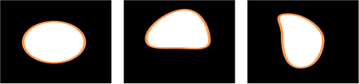
The Randomize Shape behavior allows you to animate the control points of a shape by applying a random offset to each point of the shape. This behavior is useful for creating rapid and varied effects on a shape.
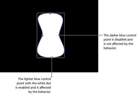
When the Randomize Shape behavior is applied to a shape, all control points of the shape are affected by default. When the behavior is selected in the Layers list, affected control points appear blue with white dots in the center of the point on the blue shape behavior spline. To disable control points, click the control points. A disabled point is a darker blue with a dark dot in the center of the point.
- Apply To: A pop-up menu that defines whether the behavior is applied to the shape’s control points, tangent handles, or both points and handles.
- Points: The control points of the shape are randomized, changing their position over the duration of the behavior.
- Tangents: The control points’ tangent handles (rather than the control points) of the shape are randomized. The control points stay in a fixed position while the curves between the points are animated.
- Points and Tangents: Both the control points and handles are animated.
- Apply Mode: A pop-up menu that determines how values generated by this behavior are combined with other behaviors and keyframes that affect the same parameter. This provides you with different ways of using a Randomize behavior to modify a vertex’s preexisting values. There are four options:
- Add: Values generated by this behavior are added to other behaviors and keyframes that affect the same parameter.
- Subtract: Values generated by this behavior are subtracted from other behaviors and keyframes that affect the same parameter.
- Multiply: Values generated by this behavior are multiplied by other behaviors and keyframes that affect the same parameter.
- Add and Subtract: Values generated by this behavior are added to and subtracted from other behaviors and keyframes that affect the same parameter.
- Link: This parameter appears when you apply this behavior to a two-dimensional parameter (such as Distort) or three-dimensional parameter (such as Position or Rotation) that consists of X, Y, and/or Z values. Select this checkbox if you want the transformation applied to the X and Y vertices to be the same. For instance a +10 change to X will result in an identical +10 change to Y.
The Randomize Shape HUD contains the Amount, Multiplier, Apply To, Frequency, Noisiness, Link, and Preserve Angle parameters.
Sequence Paint
The Sequence Paint behavior allows you to animate the individual dabs of a paint stroke in sequence over time. This is the only way to animate the dabs individually—keyframing the stroke parameters or applying other behaviors affects all dabs in the stroke uniformly.
The Sequence Paint behavior is very similar to the Sequence Text and Sequence Replicator behaviors, which allow you to animate the Rotation, Color, Opacity, Scale, and Position parameters in sequence through the characters of a text layer or the elements of a replicator pattern. The Sequence Paint behavior adds Width to that list of parameters, allowing you to create sequenced animation through the dabs of a paint stroke.
For an example of using a sequence behavior, see Using the Sequence Replicator Behavior.
- Parameter: Use the Add and Remove pop-up menus to add and remove parameters to the sequence. After you add the parameter, additional controls appear in the Behaviors Inspector. Adjust those controls to create a sequence animation based on the difference between the original value of the dabs and the modified value. There are six menu options and related controls:
- Rotation: Specifies (in degrees) the rotation of the stroke dabs. You can rotate the dial or use the value slider. Click the disclosure triangle next to the Rotation parameter to reveal separate X, Y and Z Rotation controls.
- Color: Specifies a color to use to tint the stroke dabs. You can click the color well to choose a color, or open the disclosure triangle and use the Red, Green, and Blue sliders or value fields.
- Opacity: Defines the opacity of the stroke dabs. Set a new value using the slider.
- Scale: Defines the scale of the stroke dabs. Click the disclosure triangle next to the Scale parameter to reveal separate X Scaling and Y Scaling subparameters to scale the width and height of the dabs separately. By default, Scale is set to 100%—the size of the stroke dabs is equal to the original size defined in the stroke parameters.
- Width: Defines the width of the dabs. Unlike Scale, Width adjustments will alter the size of the dab while also maintaining the spacing between each dab. Set a new value using the slider.
- Position: Defines the offset of the dabs from their original position. Click the disclosure triangle next to the Position parameter to reveal separate X, Y, and Z Position subparameters. For example, to create an animation in which the dabs move upward in the Y axis over the paint stroke, enter a positive value in the Y Position field.
- Sequencing: A pop-up menu that Specifies how the sequence animation—the value change from the original parameter value to the value set in the Sequence Paint parameters—moves through the dabs of the stroke. The starting point for the sequence animation is based on the first control point of the paint stroke. There are five options:
Note: To change the start point of the shape, select the shape, and choose the Edit Points tool from the 2D tools shortcut menu in the toolbar. Then Control-click a control point and choose Set Start Point from the shortcut menu.
- To: Specifies that the animation begins at the original value of the dabs and moves to the value set in the Sequence Paint behavior for that parameter. For example, if the original opacity value of a stroke is 100%, and opacity is set to 0% in the Sequence Paint parameters, the dabs begin completely opaque and become completely transparent.
- From: Specifies that the animation moves from the value set in the Sequence Paint behavior to the original value of the stroke. For example, if the original opacity value of a stroke is 100%, and opacity is set to 0% in the Sequence Paint parameters, the dabs begin completely transparent and become completely opaque. This is the opposite of the To Sequencing option.
- Through: Specifies that the sequence goes through a full animation cycle starting at the original value of the stroke, moves to the value set in the Sequence Paint behavior, and then returns to the original value of the stroke. For example, if the original opacity value of a stroke dab is 100%, and opacity is set to 0% in the Sequence Paint parameters, the dabs begin completely opaque, become transparent, and then become completely opaque again.
- Through Inverted: Specifies that the sequence goes through an inverted animation cycle starting from the value set in the Sequence Paint behavior, moving to the original value of the stroke, and then returning to the value set in the Sequence Paint behavior. For example, if the original opacity value of a stroke is 100%, and opacity is set to 0% in the Sequence Paint parameters, the dabs begin completely transparent, become opaque, and then become completely transparent. This is the opposite of the Through option.
- Custom: Allows you to keyframe how the animation moves through the values set in the Sequence Paint parameters over a stroke. Each dab undergoes the same value sequence. When Custom is selected, added parameters must be animated to yield any effect.
- Unit Size: A pop-up menu that specifies whether the sequence animation is applied to the stroke as a whole, to its individual dabs, or to a custom range.
- Dab: Applies the sequence animation over each dab as its own entity. Dab is the default setting.
- All: Applies the sequence animation to all stroke dabs simultaneously.
- Custom: Allows you to specify the percentage of dabs on the stroke affected by the sequence animation at once. Although you can create keyframes for the Custom option, it is not required to affect the sequence. Custom allows you to define an area of dabs affected by the sequence.
- Traversal: A pop-up menu that sets the action of the sequence behavior to Constant Speed, Ease In, Ease Out, Ease In/Out, Accelerate, Decelerate, or Custom.
- Constant Speed: Moves the animation from the origin of the paint stroke through the end of the stroke at a constant speed.
- Ease In: The sequence animation begins slowly and increases to normal speed as it moves through the paint stroke.
- Ease Out: The sequence animation begins at normal speed and slows toward the end of the paint stroke.
- Ease In/Out: The sequence animation begins slowly, increases to normal speed as it moves toward the middle of the stroke, and slows as it reaches the end of the paint stroke.
- Accelerate: The sequence animation increases in speed.
- Decelerate: The sequence animation decreases in speed.
- Custom: Allows you to keyframe how the animation moves through the paint stroke. When you choose Custom from the Traversal pop-up menu, the Location parameter replaces the Loops parameter.
- Location: Available only when Custom is selected from the Traversal pop-up menu, this slider defines the location of the stroke where the animation is in effect.
For more information on using the Custom Traversal option, see Using the Sequence Replicator Custom Traversal Option.
- End Condition: A pop-up menu that determines how the sequence animation is repeated over the duration of the sequence behavior. This parameter has no effect for Loop values less than or equal to 1. The End Condition options are:
- Hold: Completes the sequence animation cycle one time, then starts it over again from the beginning (after the last dab in the sequence has completed its animation).
- Wrap: Treats the sequence animation as a continuous loop so the spread wraps from the last dab in the sequence to the first dab.
- Ping Pong: Completes the sequence animation cycle forward, then completes the animation backward, then forward, and so on.
The Sequence Paint HUD contains the Sequencing, Unit Size, Spread, Traversal, Loops, and End Condition parameters.
Track Points
This behavior allows you to track the control points of a shape or mask to a moving clip or animated object, or to apply existing tracking data to a shape or mask. For information on using the Track Points behavior, see Shape Track Points Behavior.
Wriggle Shape
This behavior works similarly to the Randomize behavior, but with a slower effect (think of a shape that’s had one too many espressos before dance class).
When the Wriggle Shape behavior is applied to a shape, all control points of the shape are affected by default. When the behavior is selected in the Layers list, affected control points are highlighted in white on the blue shape behavior spline. To disable control points, click the control points. A disabled point appears blue.
- Apply To: A pop-up menu that defines whether the behavior is applied to the shape’s control points, tangent handles, or both points and handles.
- Points: The control points of the shape are wriggled, changing their position over the duration of the behavior.
- Tangents: The control points’ tangent handles (rather than the control points) are wriggled. The control points stay in a fixed position while the curves between the points are animated.
- Points and Tangents: Both the control points and tangent handles are animated.
- Apply Mode: A pop-up menu that determines how values generated by this behavior are combined with other behaviors and keyframes that affect the same parameter. This provides you with different ways of using a Wriggle behavior to modify a vertex’s preexisting values. There are four options:
- Add: Values generated by this behavior are added to other behaviors and keyframes that affect the same parameter.
- Subtract: Values generated by this behavior are subtracted from other behaviors and keyframes that affect the same parameter.
- Multiply: Values generated by this behavior are multiplied by other behaviors and keyframes that affect the same parameter.
- Add and Subtract: Values generated by this behavior are added to and subtracted from other behaviors and keyframes that affect the same parameter.
The Wriggle Shape HUD contains the Amount, Multiplier, Apply To, Frequency, Wriggle Offset, Noisiness, Link, and Preserve Angle parameters.
Write On
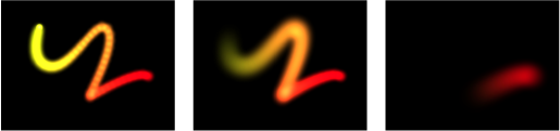
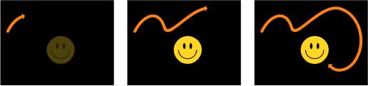
The Write On behavior provides a quick way to draw a paint stroke or outline on the Canvas over time. This allows you to create a handwritten text effect, create the ever-popular old serial travel map effect, create a hand-sketched alpha mask for a transition or reveal, create an animated graph for a business presentation, produce graphics to prevent monitor burn-ins, and so on. The behavior can be applied to a paint stroke created with the Paint Stroke tool or added to an existing shape. You can have the shape draw, erase, draw and erase, draw in reverse, and so on, over time.
When Write On is applied to a filled shape with an outline, only the outline of the shape is drawn.
Note: You can manually animate the First Point Offset and Last Point Offset parameters in the Style pane of the Shape Inspector to achieve the same effect as the Write On behavior.
- Shape Outline: This pop-up menu determines whether the stroke is drawn, erased, or drawn and erased.
- Draw: Draws the stroke over the duration of the behavior.
- Erase: The stroke is completely drawn at the beginning of the behavior and is erased over the duration of the behavior.
- Draw and Erase: The stroke is drawn, then erased over the duration of the behavior.
- Erase and Draw: The stroke is completely drawn at the beginning of the behavior, is erased, then is drawn again.
- Stroke Length: This slider defines the length, as a percentage, of the drawn or erased stroke. A value of 100% uses the entire length of the stroke, bounded by the First Point Offset and Last Point Offset parameters. If Stroke Length is set to 50%, when 50% of the stroke is drawn on, it begins to erase (from the beginning of the stroke) so only half of the length of the stroke is ever displayed over the duration of the behavior.
- Speed: A pop-up menu that defines the stroke’s “draw-on” velocity from the first to the last point in the stroke. There are nine options:
- Constant: The stroke is drawn at a steady speed from the first to the last point in the stroke.
- Ease In: The drawing of the stroke starts at a slow speed, then reaches and maintains a steady speed through the last point on the stroke.
- Ease Out: The drawing of the stroke starts at a steady speed, then slows down as it gradually decelerates to a stop at the last point of the stroke.
- Ease Both: The drawing of the stroke slowly accelerates from the first point on the stroke, and then slows down as it gradually decelerates to a stop at the last point of the stroke.
- Accelerate: The stroke is drawn with increasing speed.
- Decelerate: The stroke is drawn with decreasing speed.
- Natural: The speed in which the stroke is drawn along the path is determined by the shape of the path. For example, if the stroke is a U-shape curve, the stroke is drawn along more quickly as it moves toward the low point of the U, and more slowly as it moves up the edges.
- Recorded: This option only appears if there is a recorded time over which the stroke was drawn. In other words, if a shape is converted to a paint stroke, this parameter does not appear. If the paint stroke is created with the Paint Stroke tool in the toolbar (using a stylus or mouse), this option does appear.
- Custom: Custom allows you to draw the stroke along its path by setting keyframes for the stroke’s speed from 0 to 100%. In other words, you determine what portion of the stroke is drawn along its path in time.
- Custom Speed: This parameter becomes available when Speed is set to Custom. You can modify the Custom Speed velocity curve in the Keyframe Editor. For example, you can keyframe custom values to draw a stroke forward to a specific percentage of its path, then backward, then forward, and so on before it reaches the end of the animation.
The Write On HUD contains the Shape Outline, Stroke Length, Stroke Offset, Direction, Speed, and Custom Speed parameters.
Creating Write On Paint Strokes
You can create a paint stroke that appears over the course of several frames by recording the stroke as it is drawn, or you can apply the Write On behavior to an existing shape to draw its outline on over time.
Creating a Write On Paint Stroke Using the Paint Stroke Tool
This section describes creating a “write-on” paint stroke using the Paint Stroke tool in the toolbar. To create a paint stroke that appears over the course of several frames, select the Write On checkbox in the Paint Stroke Tool HUD. After you create the stroke, additional parameters become available in the Behaviors Inspector.
In the toolbar, click the Paint Stroke tool (or press P).
The Paint Stroke Tool HUD appears. If the HUD does not appear, press F7 or D.
In the Tool HUD, select the Write On checkbox and any other desired stroke settings.
In the Canvas, create your stroke.
When you complete stroke, press Esc to exit the paint mode.
The Paint Stroke Tool HUD is replaced with the Shape HUD. In the Layers list, a Write On Shape behavior is applied to the stroke. To modify the Write On parameters, select the behavior and use the HUD or the Behaviors Inspector.
The speed at which the stroke is “painted” (including the duration it took to draw the stroke) is mapped over the time extent (in frames) of the stroke. The faster a stroke is drawn, the shorter the duration of the Write On behavior.
Note: If your Motion Project Preferences Create Layers At option is set to Current Frame, the paint stroke is created at the current playhead position. If set to Start of Project, the stroke is created at frame 1.
Play back your project. The stroke is “painted on” as the project plays.
To modify the speed at which the stroke is painted, adjust the duration of the behavior in the Timeline or mini-Timeline.
You can also modify additional parameters, such as customizing the speed at which the stroke is drawn, drawing on only a percentage of the stroke, offsetting the stroke, or drawing the stroke in reverse. These parameters are available in the Write On behavior, described above.
Creating a Write On Paint Stroke Using an Existing Shape
You can apply the Write On behavior to an existing shape to draw its outline over time. Because the Write On behavior only affects outlines, Outline must be enabled in the Shape parameters.
Note: When a Write On behavior is added to an existing shape, the behavior spans the duration of the shape to which it is applied.
Select the shape you want to use and select its Outline checkbox in the HUD or Shape Inspector.
Note: You can leave the Fill checkbox selected, but only the outline is affected by the Write On behavior.
In the toolbar, choose Shape > Write On from the Add Behavior pop-up menu.
The Write On behavior appears in the Layers list. If the playhead is located at the start of the shape, the visual shape disappears and only the path is visible.
Play the project (press the Space bar).
The outline is drawn over the length of the behavior.
To adjust the speed at which the stroke is painted, adjust the duration of the behavior in the Timeline or mini-Timeline.
To adjust the properties of the stroke, use the Shape Inspector. For more information, see Shape Parameters.