Shape Parameters
The Shape Inspector appears when you select a shape in the Canvas, Layers list, or Timeline. This Inspector contains the Style, Stroke, Advanced, and Geometry panes. These panes contain parameters that let you further customize the shape.
Style Pane Controls in the Inspector
The Shape Inspector’s Style pane contains controls to modify the fill and outline of a shape, including changing the brush type for an outline or paint stroke. The parameters are grouped into two main categories of controls: Fill and Outline.
Style Pane Parameters
The Style pane is available for all shapes and paint strokes.
- Fill: By default, this checkbox is selected for new closed shapes, which are filled with the color specified in the Fill Color controls. The Fill parameters allow you to modify the fill of a shape.
- Fill Mode: This pop-up menu sets how a shape is filled. There are two options:
- Color: When this option is selected, the Fill Color controls appear and allow you to pick a color to fill the shape. Fill opacity allows you to set the opacity of the fill.
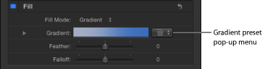
- Gradient: When this command is selected, the Gradient editor appears, as well as the Gradient preset pop-up menu. The Gradient preset pop-up menu allows you to apply a preset gradient (from the Gradients category in the Library) to the selected shape. In addition to the preset gradients, any custom gradients you have saved to the Library also appear in this list. Click the disclosure triangle to the left to display the Gradient editor, which you can use to create your own custom color and opacity gradients. For more information on using the gradient editors, see Gradient Controls. The controls for the Gradient editor are identical to the gradient controls for text, with one exception. The text gradient parameters include a dial to control the angle of the gradient. The shape gradient parameters use Start and End point controls, which are available in the Inspector or in the onscreen controls.
- Fill Color: These controls, available when Fill Mode is set to color, let you pick a color fill for the shape. For more information on using the color controls, see Color Controls.
- Falloff: Controls how “steep” the feathering is. Higher values result in feathering that’s pushed in farther inward, so the edge of the feathering effect is more transparent. Lower values result in the “core” of the feathering effect being pushed farther outward, so the edge of the feathering effect is less transparent.
- Outline: When this checkbox is selected, the shape outline appears in the Canvas and the outline controls become available. By default, this checkbox is deselected for closed shapes and is selected for open shapes and paint strokes. When you select the Outline checkbox, the Brush Type, Brush Color, Brush Opacity, Width, First and Last Point Offsets, Order, and other controls become available.
- Brush Type: This pop-up menu lets you choose a Solid, Airbrush, or Image brush to create the outline.
- Solid: The default setting. Creates a solid outline along the shape spline or paint stroke.
- Airbrush: Creates an outline made up of editable brush strokes referred to as dabs. You can set the dabs to be close together so the line appears solid, or you can space the dabs further apart. When Brush Type is set to Airbrush, the Stroke and Advanced panes become available in the Shape Inspector.
- Image: Allows you to use a layer as a dab source. When Brush Type is set to Image, the Stroke and Advanced panes become available in the Shape Inspector.
- Brush Color: Lets you pick a color to use for the outline or paint dabs. These color controls are identical to the shape Fill Color controls (and all color controls throughout Motion).
Note: When Stroke Color Mode (in the Stroke pane) is set to Color Over Stroke or Pick From Color Range, Brush Color is not available.
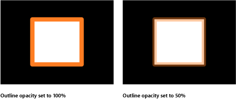
- Brush Opacity: Defines the opacity of the entire stroke, regardless of the Brush Type setting.
Note: When Stroke Color Mode (in the Stroke pane) is set to Color Over Stroke or Pick From Color Range, the Brush Color and Brush Opacity parameters are unavailable. When Stroke Color Mode (in the Stroke pane) is set to Use Brush Color, you can adjust the opacity, in the Stroke pane, to change over the course of the stroke. For more information on using the Opacity Over Stroke parameter, see Stroke Pane Controls in the Inspector.
The Brush Opacity control allows you to define a different opacity value for a shape and its outline.
- Brush Source: When Image is the selected Brush Type, drag a layer into the Brush Source image well for use as the outline’s brush source. You can use images, image sequences, QuickTime movies, text, and shapes as the brush source.
When a movie or image sequence is the brush source, additional parameters appear. For more about Movie or image sequence parameters, see Additional Parameters When Brush Source Is a QuickTime Movie or Image Sequence.
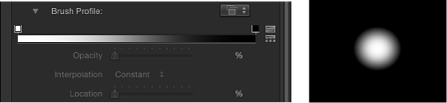
- Brush Profile: Available when Airbrush is the selected Brush Type, this gradient editor allows you to create varying levels of opacity within the brush. The brush profile uses the same opacity controls as a standard gradient editor. For more information, see Gradient Controls.
The default gradient creates a soft airbrush.
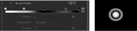
Modify the Brush Profile opacity gradient to create new brush looks.
- Width: A slider that changes the width of a shape’s outline or width of a paint stroke’s dabs. On paint strokes, width adjustments will alter the size of the dab while also maintaining the spacing between each dab.
Note: If you used the pressure parameters in the Paint Stroke Tool HUD to create variations in the stroke when the stroke was created, adjusting the Width parameter affects the width of the stroke uniformly.
- Additive Blend: By default, dabs are composited together using the Normal blend mode. Select this checkbox to composite all overlapping dabs together using the Additive blend mode. This blend mode occurs in addition to whichever compositing method is already in use. This checkbox is only available when Brush Type is set to Airbrush or Image.
- First Point Offset: This parameter allows you to offset and animate the start point of the outline. This is very useful for effects such as drawing a line across a map over time.
You can also use the Shape Write On behaviors to draw a stroke or outline over time. For more information, see Write On.
Additional Parameters When Brush Source Is a QuickTime Movie or Image Sequence
A collection of additional settings appear when the Brush Source is set to a multi-frame object such as a QuickTime movie or Image sequence.
- Random Start Frame: A checkbox that introduces variation to image brush strokes using multi-frame source objects. If the checkbox is selected, each dab will pull from a random frame in the source. The dab will start animating from this random frame or remain still, depending on whether the Play Frames checkbox is selected or deselected. This pattern of randomness can be adjusted by using the Random Seed button under the Stroke pane.
- Source Start Frame: Click the Source Start Frame disclosure triangle to display a mini-curve editor that allows you to define the frame where playback of the source clip begins in the paint dabs. The Source Start Frame default keyframe value is 0. You can change the start frame for all dabs, or you can create a curve so start frames vary over the length of the stroke (different dabs use different start frames). For example, if the first Source Start Frame value is 50, each dab begins playback at frame 50. If you create an animation curve that begins at 50 and ends at 250, each dab begins clip playback at a progressively later frame.
The Play Frames checkbox must be selected for playback to occur. If Play Frames is deselected, you can display different still frames over the length of the stroke. This parameter only appears if Random Start Frame is deselected.
Note: For information on using the mini-curve editor, see Mini-Curve Editor.
When you click the Source Start Frame disclosure triangle, the Stroke Length and Source Start Frame parameters become available.
- Stroke Length: Stroke Length is mapped horizontally on the mini-curve editor graph and provides a visual representation of the position of the changes in start frame value (keyframes) over the length of the stroke. Use the sliders or enter a number into the value field to change the value of the selected keyframe.
Stroke Pane Controls in the Inspector
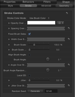
After you create an airbrush or image paint stroke using the Paint Stroke tool, a set of paint stroke controls becomes available, combining controls similar to those of a particle system or replicator. Use these controls to set the Stroke Color Mode and Brush Scale parameters, and to adjust the Opacity, Spacing, Width, and Angle Over Stroke parameters.
Stroke Pane Parameters
The Stroke pane becomes available when Airbrush or Image is selected from the Brush Type pop-up menu in the Style pane.
- Stroke Color Mode: Use this pop-up menu to specify how the color is applied to the stroke over its length. There are three options:
- Use Brush Color: Uses the color of the brush as defined by the Brush Color parameter in the Style pane. The stroke is a solid color over its length. When you choose Use Brush Color from the Stroke Color Mode pop-up menu, the Opacity Over Stroke control becomes available.
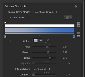
- Color Over Stroke: Dabs are tinted based on their position over the length of the paint stroke. When you choose this option, the Color Over Stroke control becomes available.
- Pick From Color Range: Dabs are tinted at random, with the range of possible colors defined by a gradient editor. A point on the gradient is randomly chosen, so the relative sizes of each color region determine the frequency of the color being used.
- Opacity Over Stroke: An opacity control that appears when Stroke Color Mode is set to Use Brush Color. Use it to change the opacity of dabs based on their location on the stroke. This gradient control is limited to grayscale values, which are used to represent varying levels of transparency. White represents solid dabs, progressively darker levels of gray represent decreasing opacity, and black represents complete transparency. A simple white-to-black gradient represents a stroke that is solid at its start, but fades out gradually over its length until finally vanishing at the end. For information on using gradient editors, see Gradient Controls.
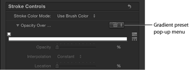
Use the gradient preset pop-up menu to load a custom or preset opacity gradient into the gradient editor.
Note: None of the default gradients have opacity gradients. If a color gradient preset is selected, it has no effect on the opacity gradient.
- Color Over Stroke: A gradient editor defining the range of color of the stroke, beginning with the leftmost color in the gradient, and progressing through the range of colors until reaching the rightmost color at the end of the stroke. Gradual color changes do not appear in each dab, only across the stroke as a whole. An opacity bar appears at the top of the gradient editor. For information on using gradient editors, see Gradient Controls.
- Color Range: A gradient editor that appears when the Stroke Color Mode is set to Pick From Color Range. Use it to define a range of colors used to randomly tint the stroke’s paint dabs. The direction of the gradient colors is not relevant, only the number of colors that appear in the gradient. The Color Range parameter has the same controls as the Color Over Stroke parameter. For information on using gradient editors, see Gradient Controls.
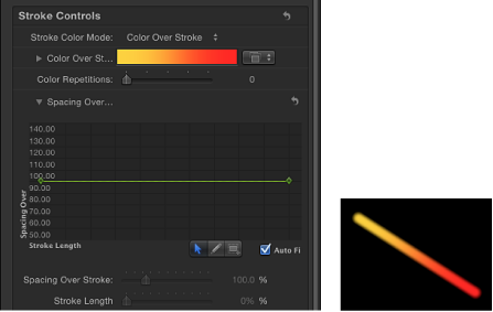
- Spacing Over Stroke: This mini-curve editor allows you to customize the spacing of the dabs over the length of the stroke. You can create a curve that gradually increases the dabs’ spacing over the length of the stroke, create a curve that varies the dabs’ spacing over the length of the stroke, and so on. Select or add a keyframe in the graph to make changes to the Spacing Over Stroke and Stroke Length parameters.
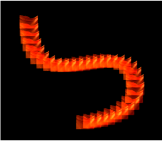
In the following illustrations, the default Spacing Over Stroke value of 100% in the mini-curve editor creates an even distribution of the dabs—based on the value set in the Spacing parameter in the Style pane. For more information on using the mini-curve editor, see Mini-Curve Editor.
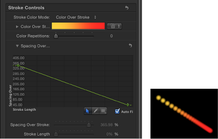
In the following illustrations, the Spacing Over Stroke curve in the mini-curve editor is adjusted so a greater value is used at the start of the stroke, and 100% is used at the end of the stroke. The dabs at the beginning of the stroke are spaced more widely apart and get closer at the end of the stroke.
Two controls let you fine-tune the curve in the graph:
- Stroke Length: Stroke Length is mapped horizontally on the mini-curve editor graph and provides a visual representation of the position of the changes in spacing value (keyframes) over the length of the stroke. Use the sliders or enter a number in the value field to change the value of the selected keyframe.
Note: For information on using the mini-curve editor, see Mini-Curve Editor.
- Fixed Brush Dabs: When animating brush strokes using behaviors or keyframes, selecting the Fixed Brush Dabs checkbox keeps the number and spacing of the dabs constant regardless of the changes in the stroke’s shape over time. The effect of this parameter is not visible when editing a paint stroke on a single frame.
- Anchor Dabs To: This pop-up menu, available when the Fixed Brush Dabs checkbox is deselected, defines how dabs are added to or removed from a paint stroke when the length of the paint stroke is modified. When the Fixed Brush Dabs checkbox is selected, dabs are anchored to the start and end of the paint stroke. There are two options:
- Start: Adds dabs to or removes dabs from the start point of a paint stroke when the length of the paint stroke is modified. The first dab on the stroke remains fixed.
- Start and End: Adds dabs to or removes dabs from the start and end points of a paint stroke when the length of the paint stroke is modified. The first and last dabs on the stroke remain fixed.
Note: Changing a shape’s control points or adjusting the Width or Spacing parameters (in the Style pane) or Spacing Over Stroke and Width Over Stroke parameters (in the Stroke pane) affect the dab spacing because larger dabs can be spaced further apart.
- Width Over Stroke: This mini-curve editor allows you to customize the width of the dabs over the length of the stroke. You can create a curve that gradually increases the dabs’ width over the length of the stroke, create a curve that varies the dabs’ width over the length of the stroke, and so on. Select or add a keyframe in the graph to make changes to the Width Over Stroke and Stroke Length parameters. The start value for the dab width is based on the value set in the Width parameter in the Style pane. For more information on using the mini-curve editor, see Mini-Curve Editor.
Two controls let you fine-tune the curve in the graph:
- Stroke Length: Stroke Length is mapped horizontally on the mini-curve editor graph and provides a visual representation of the position of the changes in width value (keyframes) over the length of the stroke. Use the sliders or enter a number in the value field to change the value of the selected keyframe.
The Width Over Stroke parameter can be adjusted on the selected paint stroke in the Canvas. For more information, see Using the Width Over Stroke Onscreen Controls.
- Brush Scale: A slider and value field that allow you to change the size of the brush (the source of the dabs). Click the disclosure triangle to adjust the X and Y scale values independently. By default, Scale is set to 100%—the size of the dabs is equal to the size of the source brush. Unlike the width parameter in the Style pane, brush scale adjustments only affect the size of the dabs and don’t preserve the spacing between dabs.
- Brush Scale Randomness: Defines an amount of variance in the scale of the stroke’s brush. A value of 0 results in no variance—all dabs in the stroke are the same size. A value greater than 0 introduces a variance. The scale for an individual dab is defined by the Scale parameter, plus or minus a random value falling within the Brush Scale, Width Over Stroke, and Width (in the Style pane) parameters. Click the disclosure triangle to adjust the X and Y values independently.
- Brush Angle: Specifies (in degrees) the rotation of the stroke dabs. Using the default dial or value slider modifies the Z angle. When the Local 3D checkbox is selected, additional Brush Angle Randomness controls become available. Click the disclosure triangle to expose X, Y, and Z rotation dials and the Animate pop-up menu.
- Animate: Only available when the Local 3D checkbox is selected, this pop-up menu allows you to change the interpolation for animated 3D rotation channels. Click the Brush Angle disclosure triangle to display the Animate parameter. By default, Animate is set to Use Rotation.
- Use Rotation: The default interpolation method. Pattern elements rotate from their start rotation to their final rotation. Depending on the animation, the elements may twist this way and that before reaching their final orientation (the last keyframed value). For example, if the X, Y, and Z angle parameters are animated from 0 degrees to 180 degrees in a project, the elements rotate on all axes before reaching their final orientation.
- Use Orientation: This alternate interpolation method provides smoother interpolation but does not allow multiple revolutions. It interpolates between the pattern elements’ start orientation (first keyframe) to their end orientation (second keyframe).
- Angle Over Stroke: This mini-curve editor allows you to customize the Z rotation (in degrees) of the dabs over the length of the stroke. You can create a curve that gradually increases the dabs’ angle over the length of the stroke, a curve that varies the dabs’ angle over the length of the stroke, and so on. Select or add a keyframe in the graph to make changes using the Angle Over Stroke and Stroke Length controls.
- Stroke Length: Stroke Length is mapped horizontally on the mini-curve editor graph and provides a visual representation of the position of the changes in angle value (keyframes) over the length of the stroke. Use the sliders or enter a number in the value field to change the value of the selected keyframe.
- Brush Angle Randomness: Defines an amount of variance in the rotation of the stroke dabs. A value of 0 results in no variance—all dabs have the same rotational value. A value greater than 0 introduces a variance. The angle for an individual dab is defined by the Brush Angle and Angle Over Stroke parameters, plus or minus a random value falling within the Brush Angle Randomness.
Using the default dial or value slider modifies the Z angle. To individually modify the rotation of the dabs in X, Y, and Z space, or to access the Animate parameter, click the disclosure triangle when the Local 3D checkbox is selected.
- Animate: Only available when the Local 3D checkbox is selected, this pop-up menu allows you to change the interpolation for animated 3D rotation channels. Click the Brush Angle Randomness disclosure triangle to display the Animate parameter. By default, Animate is set to Use Rotation.
- Use Rotation: The default interpolation method. Pattern elements rotate from their start rotation to their final rotation. Depending on the animation, the elements may twist this way and that before reaching their final orientation (the last keyframed value). For example, if the X, Y, and Z Angle parameters are animated from 0 degrees to 180 degrees in a project, the elements rotate on all axes before reaching their final orientation.
- Use Orientation: This alternate interpolation method provides smoother interpolation but does not allow multiple revolutions. It interpolates between the pattern elements’ start orientation (first keyframe) to their end orientation (second keyframe).
- Local 3D: This checkbox allows you to take advantage of the Motion 3D workspace. When the Local 3D checkbox is selected, the following become possible:
When the Face Camera checkbox is selected, paint dabs actively face the camera when the camera or stroke is rotated and/or animated.
When the Dab Depth Ordered checkbox is deselected, dab ordering remains consistent when the paint stroke (or the camera) is rotated in X or Y space. When this checkbox is selected, the dabs jump in front of each other each time the stroke rotates 180 degrees. In other words, this checkbox draws the dabs in the stroke according to each dab’s actual 3D position in the project. Dabs that are closer to the camera appear closer; dabs that are farther from the camera appear more distant.
When the Dynamics checkbox is selected in the Advanced pane, a paint stroke acts similarly to an emitter—the dabs become particles. When the Local 3D checkbox is selected, the dabs are animated in 3D space. When the Local 3D checkbox is deselected, the particles are animated in X and Y space only. For more information on Dynamics, see Advanced Pane Controls In the Inspector.
When the Dynamics checkbox is selected in the Advanced pane, dabs can be pulled out of their plane when some Simulation behaviors are applied. For example, if a paint stroke has an applied Attracted To behavior (with the Affect Subobjects checkbox selected), and the target layer is in a different location in Z space, the dabs are pulled into Z space and move toward the target layer. The paint stroke must be a member of a 3D group to be pulled out of the X and Y planes by a behavior.
Use the following guidelines when working in 3D with paint strokes:
Even in a 2D project, a paint stroke’s general properties can be adjusted in 3D space. For example, you can modify the Z parameter using the Position, Scale, Rotation, and Anchor Point controls in the Properties Inspector.
Paint strokes do not receive reflections (controlled in the Properties Inspector) unless the Local 3D checkbox is deselected.
Paint strokes do not cast shadows (controlled in the Properties Inspector) unless the Local 3D checkbox is deselected.
Lighting does not effect paint strokes unless the Local 3D checkbox is deselected.
Important: Although the Local 3D checkbox is selected, paint strokes do not intersect with the “global” 3D world. This means that paint strokes can exist in 3D space, but do not intersect with objects that exist inside their own group, or objects in other groups. A 3D paint stroke is composited with the rest of the objects in the project based on layer order.
- Face Camera: Available only when the Local 3D checkbox is selected, the stroke dabs actively face the camera if the camera is rotated or if the paint stroke is rotated and/or animated when this checkbox is selected. When the Face Camera checkbox is deselected, the elements face forward in the replicator pattern and appear flat (unless the source layer or paint dabs are rotated in 3D space).
Because paint source dabs are 2D (flat) objects, the pattern elements are not visible when you use the orthogonal camera views, such as Left, Right, and Top (unless the source layer or dabs are rotated in 3D space). This is because orthogonal views are at right angles (perpendicular) to the elements. For more information on using cameras, see Cameras.
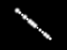
- Jitter: This slider and value field allow you to create a little chaos in your paint dabs. The higher the value, the more dispersed the dabs. Click the disclosure triangle to display the individual X and Y controls. Jitter can be animated so the dabs behave like particles.
- Jitter: Moves the dabs both parallel and perpendicular to the stroke’s curves at its control points.
- X: Moves the dabs parallel to the stroke’s curves at its control points.
- Y: Moves the dabs perpendicular to the stroke’s curves at its control points.
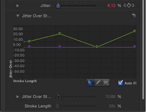
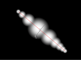
- Jitter Over Stroke: This mini-curve editor allows you to customize the scatter of the dabs over the length of the stroke. You can create a curve that gradually increases the dabs’ jitter over the length of the stroke, a curve that varies the dabs’ jitter over the length of the stroke, and so on. Select or add a keyframe in the graph to make changes using the Jitter Over Stroke and Stroke Length controls.
- Jitter Over Stroke: This parameter is divided into two channels. Click the disclosure triangle to display the individual X and Y controls. Use the X parameter to adjust keyframes that define the amount of dab movement parallel to the stroke’s curve at specific points along the stroke (red curve). Use the Y parameter to adjust keyframes that define the amount of dab movement perpendicular to the stroke’s curve at specific points along the stroke (green curve). Use the Jitter Over Stroke parameter to adjust the amount of dab movement in both directions at specific points along the curve (adjusts red and green curve simultaneously).
- Stroke Length: Stroke Length is mapped horizontally on the mini-curve editor graph and provides a visual representation of the position of the changes in jitter value (keyframes) over the length of the stroke. Use the sliders or enter a number in the value field to change the value of the selected keyframe. For more information on using the mini-curve editor, see Mini-Curve Editor.
- Random Seed: The variation of the Jitter, Brush Angle Randomness, and Brush Scale Randomness parameters (in the Stroke pane) and the Life, Speed, and Spin Randomness parameters (in the Advanced pane) are based on the number shown here. If you don’t like the current random distribution of the dabs, you can change the seed number by typing a new number or clicking Generate. The Jitter value must be 1 or more for this parameter to have any effect.
Using the Width Over Stroke Onscreen Controls
The Width Over Stroke control can be manipulated using the mini-curve editor, or you can adjust its keyframe values in the Canvas. An editable control appears at each keyframe in the stroke.
In the Canvas, Control-click the paint stroke, then choose Stroke from the shortcut menu.
Small control points (+) appear at each keyframe along the red spline.
Click the control point that represents the keyframe you want to adjust.
Control handles appear on either side of the control point.
To increase the width of the dabs, drag away from the point; to decrease the width of the dabs, drag toward the point.
To change the position of a width keyframe, drag the control point left or right to move it along the length of the stroke. (Keyframes can be dragged over one another.)
The mini-curve editor is updated as you make your onscreen adjustments.
To add width keyframes, Option-click or double-click the red spline.
To delete width keyframes, select the keyframe and press Delete.
Advanced Pane Controls In the Inspector
The Advanced pane of the Shape Inspector contains controls that allow the dabs of a paint stroke to be animated like particles. Unlike particles, dabs are only “born” one time; but they can age and die like particles. Dynamic dabs share several controls with particles, such as Emission Angle, Life, Speed, and Spin. When the Dynamics checkbox is deselected, dabs are immortal.
When you select a shape created with the Paint Stroke tool, Pen Pressure and Pen Speed controls appear in the Advanced pane.
Note: All Dynamics controls can be animated using keyframes or by applying Parameter behaviors to the individual parameters.
Advanced Pane Parameters
The Advanced pane becomes available when Airbrush or Image is selected from the Brush Type pop-up menu in the Style pane.
- Dynamics: When this checkbox is selected, the dabs of a paint stroke become particles.
Note: When a Simulation behavior is applied to a paint stroke, the Affect Subobjects parameter only appears in the behavior if Dynamics is selected for the paint stroke. Click the disclosure triangle to reveal the following additional Dynamics controls:
- Life Randomness: A slider and value field that define an amount of variance in the life of the paint dabs. A value of 0 results in no variance—all dabs from the selected stroke share the same life span. A value greater than 0 introduces a variance defined by the Life parameter, plus or minus a random value falling within the Life Randomness value.
- Speed Randomness: A slider and value field that define an amount of variance in the speed of the paint dabs. A value of 0 results in no variance—all dabs from the selected stroke move with the same speed. A value greater than 0 introduces a variance defined by the Speed parameter, plus or minus a predetermined random value falling within the Speed Randomness value.
- Spin Randomness: A dial and value slider that define an amount of variance in the spin of the paint dabs. A value of 0 results in no variance—all dabs from the selected stroke spin at the same rate. A value greater than 0 introduces a variance defined by the Spin parameter, plus or minus a random value falling within the Spin Randomness value.
- Pen Pressure: Allows you to affect the width, opacity, spacing, angle, or jitter of the paint stroke based on the pressure of your stylus on the tablet when the stroke was created. This parameter appears when you do any of the following:
Create a paint stroke using the Paint Stroke tool in the toolbar
Apply a shape style from the Shape Style pop-up menu to an existing paint stroke
Note: Only strokes drawn using a stylus and tablet will have recorded pressure variations. You can select how the pressure of the stylus affects the stroke in the Paint Tool HUD before the stroke is created or afterwards by activating this parameter in the Advanced pane.
These controls are identical to the Apply Pen Pressure (Shape behavior) parameters. For a description of the Pen Pressure parameters, see Shape Behaviors. The inspector parameters can be used in combination with these shape behaviors to affect more than one parameter (such as Opacity, Width, or Jitter) of the stroke using the same pressure data.
- Pen Speed: Allows you to affect the width, opacity, spacing, angle, or jitter of the paint stroke based on the speed of your stylus on the tablet or the speed of your mouse when the stroke was created. This parameter only appears when you do any of the following:
Create a paint stroke using the Paint Stroke tool in the toolbar
Apply a shape style from the Shape Style pop-up menu to an existing paint stroke
These controls are identical to the Apply Pen Speed (Shape behavior) parameters. For a description of the Pen Speed parameters, see Shape Behaviors. The inspector parameters can be used in combination with these shape behaviors to affect more than one parameter (such as Opacity, Width, or Jitter) of the stroke using the same pressure data.
Geometry Pane Controls in the Inspector
The Shape Inspector’s Geometry pane controls allow you to change the shape type, to close or open a shape, and to individually adjust the position of a shape’s control points using value sliders.
Geometry Pane Parameters
The Geometry pane controls are available for all shapes regardless of what is selected in the Brush Type pop-up menu in the Style pane.
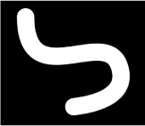
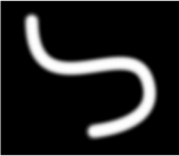
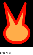
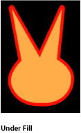
You can change a shape’s type at any time. Changing a shape’s type changes its form. For example, a single set of control points produces the following three shapes, depending on the selected Shape Type.
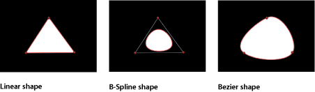
- Shape Type: Use this pop-up menu to change the type of control points used to define the shape. For example, if you originally created a Bezier shape, you can choose B-Spline from this menu to change each Bezier control point into a B-Spline control point. Changing the shape type does not move the control points, although the shape is changed, sometimes dramatically. There are three options:
- Linear: All control points are joined by hard angles, and the resulting shape is a polygon. The control points of a Linear shape lie directly on its edge.
- Bezier: Control points can be a mix of Bezier curves and hard angles, creating any sort of shape. The control points of a Bezier shape lie directly on its edge.
- B-Spline: Control points are all B-Spline points, with different degrees of curvature. B-Spline control points lie inside, outside, or on the edge of the shape, and are connected by the B-Spline frame.
Note: To show or hide the display of the B-Spline frame, choose View > Overlays > Lines.
- Closed: If you select an open shape, this checkbox is deselected. Turning this checkbox on connects the first and last points of an open shape. If you select a closed shape, this checkbox is selected. Turning this checkbox off disconnects the first and last points, converting the object into an open shape.
- Preserve Scale: This checkbox controls whether the Roundness setting is absolute, or relative to the overall shape size. When this parameter is enabled, the roundness will remain at the same approximate percentage of curvature as the object is scaled. When it is disabled, the curvature will vary as the overall shape changes size.
- Control Points: Click the disclosure triangle to display the position parameters for the shape control points. Use the value sliders to adjust the position of a control point.
The Control Points parameter also contains an Animation menu, which allows you to add keyframes, reset the shape’s animation, display the animation curve in the Keyframe Editor, and so on. For more information on using the Animation menu, see Animation Menu.