Cameras
In 3D mode, anything you see in the Canvas represents the viewpoint of a camera, either a default reference camera or a scene camera that you create. You can create cameras to look at your scene from different points of view. You can place, animate, and apply behaviors to cameras in your scene. Creating multiple cameras lets you make different cameras active at different times, allowing you to “cut to” different views over the course of the project.
Creating a Scene Camera
The scene cameras that you create are used for rendering output. Scene cameras appear in the Canvas as wireframe camera icons and as objects in the Layers list and Timeline.
Choose Object > New Camera (or press Command-Option-C).
A camera object is added to the Layers list, the Timeline, and the Canvas (represented by a wireframe icon). The 3D Transform tool in the toolbar becomes active, the Camera HUD appears (if it isn’t visible, press F7), and the Camera controls in the Inspector become available.
Active Camera
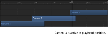
If a scene contains more than one camera, the topmost camera in the Layers list and in the Timeline at the current frame is the active camera. Although the active camera is the default camera used for export, you can select any scene camera to export.
Note: The active camera is not the same as the active view. The active view is the last viewport you clicked in when working with multiple viewports.
Camera Controls
You can modify a scene camera’s properties via the Camera HUD or the Camera and Properties panes in the Inspector.
- Camera Type: A pop-up menu that sets the type of camera used. There are two options: Framing (the default value) and Viewpoint. A Framing camera has its origin at the focal plane. The focal plane of a camera is a plane located at a distance equal to the camera’s focal distance along its local Z axis (or line of sight) and oriented perpendicular to the camera’s local Z axis. A Viewpoint camera has its origin at its center of projection.
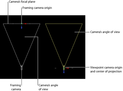
Tip: The position of a Framing camera’s origin makes it useful for orbiting moves. Rotating the camera causes it to orbit, whereas rotating a Viewpoint camera causes it to pivot—also known as panning (horizontal) or tilting (vertical).
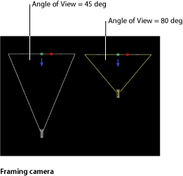
- Angle of View: A slider that sets the angle of view of the camera, which is the number of degrees in which the camera sees. Values range from 0 to 180 degrees.
Note: When you animate the Angle of View parameter on a Framing camera, the result is an opposing dolly effect. An opposing dolly zooms in the opposite direction that the camera moves. When you animate the Angle of View parameter on a Viewpoint camera, the result is a regular camera zoom.
- Far Fade: A slider that sets the softness factor for the far plane. The softness factor sets a boundary range over which far objects fade out.
Note: Camera depth of field parameters are also contained in this window. For a complete description of these controls see Depth of Field.
The Camera HUD contains the Camera Type, Angle of View, Focal Length, and DOF Blur Amount parameters, which are also available in the Inspector. The Camera HUD also contains 3D transform controls. For more information, see 3D Transform HUD Controls.
Scaling, Positioning, and Animating Cameras
Various controls allow you to scale, position, walk, and animate cameras. After you position cameras in a project, you can select a single camera view using the Isolate command. For more information on using the Isolate command, see Isolate.
Scaling a Camera
You can use the Scale parameter in the Properties pane of the Inspector to scale what a camera sees. Changing the Scale value does not affect a camera’s Angle of View parameter. Changing the Scale value only affects Framing cameras.
Positioning Cameras
Cameras share the same transform properties as any other object in Motion and can be positioned in all the same ways: by using the onscreen controls and by editing parameters in the HUD or Inspector. For more information on the onscreen controls, see 3D View Tools. Additionally, cameras can be positioned using the Walk 3D View tool. For more information, see Walk 3D View.
Note: As a convenience, you can move an orthogonal camera view to display the scene from a position and orientation other than its default.
Walk 3D View
The Walk 3D View tool, located in the toolbar, allows you to position the camera in 3D space as you would in a video game, using a keyboard-and-mouse navigation method.
If you’re using a scene camera, you can also record the movement you create using the Walk 3D View tool, by creating keyframes. For more information on keyframing, see Keyframing Methods.
Note: The Walk 3D View tool is available only when Active Camera, Camera, or Perspective is selected from the Camera menu. For more information on the Camera menu, see Camera Menu.
Select the Walk 3D View tool in the toolbar.
Note: If the tool is not visible, press and hold the Pan or Zoom tool to open the pop-up menu.
The pointer changes to indicate that the Walk 3D View tool is active.
Use the Up Arrow, Down Arrow, Right Arrow, and Left Arrow keys to move the camera in 3D space; hold down the Option key while using the arrow keys to move the camera more slowly.
You can also drag in the Canvas to orient the camera.
Animating Cameras
Cameras can be animated in the Canvas by the same means used to animate any other object in a project. Cameras can also be animated through the use of behaviors, including special Camera behaviors. For more information on Camera behaviors, see Camera Behaviors.
For more information on animating with keyframes, see Keyframes and Curves.
Isolate
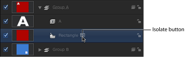
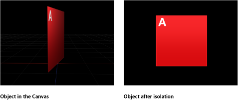
The Isolate command (and Isolate button) temporarily aligns the current view with the selected object and hides all other objects in the scene, facilitating access to distant or obscured objects.
The Isolate command is not intended for creating a camera view to be rendered or exported, but rather to temporarily restrict your view to a single object so you can modify or manipulate that object more effectively.
Select the object to isolate in the Canvas, Layers list, or Timeline.
Do one of the following:
Choose Object > Isolate (or press Control-I).
In the Layers list or Timeline, click the Isolate button.
The current view changes to align itself with the selected object, and all other objects in the scene are hidden.
When an object is isolated, a temporary camera is created and listed in the Camera menu. The camera shares its name with that of the isolated object.
Choose Object > Isolate (or press Control-I).
In the Layers list or Timeline, click the Isolate button.
Choose a different camera from the Camera menu.
Depth of Field
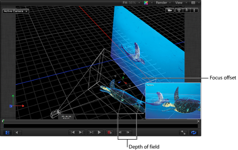
In the real world, cameras have a limited range of focus. Objects within that range appear sharp, and the further outside that range an object is, the blurrier it appears. This effect is used by camera operators to help limit which part of a scene the viewer pays attention to. Motion allows you to simulate that phenomenon, thereby increasing the sense of depth in a 3D scene.
Every camera in Motion has a focus offset that determines the precise location of perfect focus. Stretching away from that point in either direction are near and far focus points, which determine the range of the depth of field.
Note: Some complex objects are not affected by depth-of-field settings. These objects include local 3D text, paint, particles, and replicators. The objects in these groups are likely spread out along the Z axis, but the camera cannot measure their relative depth and thus cannot accurately render depth of field.
Depth of Field Controls
Depth of Field settings are found in the Camera pane of the Inspector. The Depth of Field controls allow you to set a range of focus by changing the Near Focus and Far Focus parameters. Objects outside that range are blurred. You can also modify the type and amount of blur used to render the out-of-focus effect.
- Filter: A pop-up menu to set the type of blur algorithm used to render the out-of-focus areas. Choices include Gaussian or Defocus. The Defocus setting renders a more realistic effect, but may impact performance.
Tip: For best results, use Gaussian when setting up a scene, and Defocus for final output.
- Depth: A pop-up menu that sets the depth to Radial or Planar. Although radial typically exhibits more realistic results, there are some cases where it may look artificial. These include cases where the camera is set to a high DOF Blur Amount and/or the object is close to the edge of the frame, the object is very large, the object is rotated, and other similar instances. In these cases, switching to Planar may produce improved results.
Rendering Depth of Field Effects
When depth of field is employed, playback performance may be significantly impacted. To alleviate this, you can disable the effects of depth of field settings while working on other aspects of your project.
From the Render pop-up menu in the status bar, select Depth of Field (or press Option-Control-D).
When a check mark is visible next to the menu item, the effects are rendered. When no check mark is visible, all objects remain in focus.
Select the camera in the Layers list or Timeline layers list, then set the DOF Blur Amount value (in the Depth of Field parameters) to 0 in the Camera Inspector.
Camera Behaviors
Although most types of behaviors in Motion can be applied to cameras, there is an additional set of behaviors specifically designed to be applied to a camera in a 3D project. These Camera behaviors create common camera moves such as dolly moves, panning, and zooming without keyframing.
Select a scene camera in the Layers list, Timeline, or Canvas.
In the Add Behavior pop-up menu in the toolbar, choose Camera, then choose an item from the submenu.
There are six camera-specific behaviors: Dolly, Focus, Framing, Sweep, Zoom In/Out, and Zoom Layer. These behaviors are applied to a camera object.
Dolly
Moves the camera a specified distance along the camera’s Z axis.
The HUD contains the same controls as the Inspector.
Focus
Animates the camera’s Focus Offset parameter to focus on a target object. For more information on camera focus settings, see Depth of Field.
Tip: Use this behavior to perform a rack-focus effect during a scene.
The HUD contains the same controls as the Inspector.
Framing
Animates the camera along a path to position it in front of a selected object. You can control how the object fits into the frame at the ending position, and you can control the shape of the path to affect the amount of bend or curvature, as well as the apex of such a curved path. Other parameters allow you to customize the camera’s orientation along the path, the speed at which it travels, and at what point it begins orienting towards the target object.
The Framing behavior has onscreen controls to allow you to manipulate the path and ending position in the Canvas. For more information on using the Framing behavior’s onscreen controls, see Framing Behavior Onscreen Controls.
Tip: Multiple framing behaviors can be arranged consecutively to move a camera from one object to another over the course of a scene.
Warning: Applying a Framing behavior before or after a Basic Motion behavior, such as Motion Path or Throw, can create unexpected results. These behaviors can continue to affect the object even after the behavior ends. For example, If a Framing behavior is applied after a Motion Path, the residual effect of the Motion Path is combined with the path generated by the Framing behavior, resulting in the target object being framed improperly. For more about Basic Motion behaviors, see Basic Motion Behaviors.
- Up Vector: A pop-up menu providing a constraint for the camera to keep it the right way up. The pop-up menu offers the following choices: Auto, Target +X, Target –X, Target +Y, Target –Y, Target +Z, Target –Z, World +X, World –X, World +Y, World –Y, World +Z, World –Z.
Auto tries to guess which axis should be pointing up, and the other choices allow the user to specify an axis.
- Framing: A pop-up menu to choose how the target should be framed. The menu choices include:
- Fit Horizontally: Positions the camera so the full width of the target fits in the width of the frame.
- Fit Vertically: Positions the camera so the full height of the target fits in the height of the frame.
- Fit Both: Positions the camera so both width and height of the target fit in the frame.
- Simple Fit: Positions the camera so both width and height of the project fit in the frame. If the target object is larger or smaller than the project dimensions, it may not properly fill the frame.
- Custom Fit: This option appears when the Framing Offset parameter is manipulated manually.
- Offset Path Apex: A slider to set the position along the path (from the original position to the framing position) where the bend (if any) occurs if the user chooses to offset the path. It is expressed as a value between 0 and 1 (0 being at the start of the path, 1 at the end, and 0.5 being halfway along the path).
The HUD contains a subset of the controls in the Inspector.
Framing Behavior Onscreen Controls
The Framing behavior has onscreen controls that allow you to manipulate the behavior settings in the Canvas.
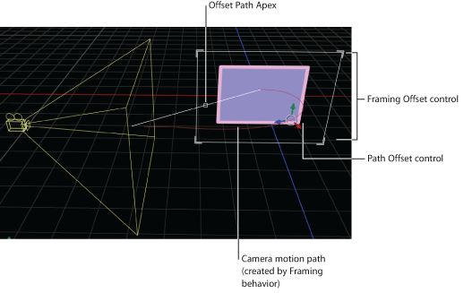
When a Framing behavior is applied and selected, The controls in the Canvas allow you to create a custom framing size and shape, and to visually adjust the Framing Offset and the Offset Path Apex.
With the Framing behavior selected in the Layers list or Timeline, click any corner of the white framing control in the Canvas.
With the Framing behavior selected in the Layers list or Timeline, drag the small white box along the diagonal white line to reposition the apex.
With the Framing behavior selected in the Layers list or Timeline, drag the onscreen control or any colored arrow.
Sweep
Pivots the camera across a specified arc.
The HUD contains the same controls as the Inspector.
Zoom In/Out
Animates the camera’s Angle of View parameter.
- Zoom: A slider that sets a proportional value to modify the camera’s Angle of View parameter. For more information about the Angle of View parameter, see Camera Controls.
The HUD contains the same controls as the Inspector.
Zoom Layer
Moves a camera to the position of a target object’s anchor point. When the camera reaches the object’s anchor point, the angle of view changes while offsetting the camera’s position based on the Zoom parameter. (This parameter is set to 0 by default so no animation of the Angle of View occurs.)
This behavior also allows you to animate the camera’s Angle of View during the camera’s movement, based on the behavior’s Transition value. For more information about the Angle of View parameter, see Camera Controls.
- Transition: A slider that determines how far into the behavior the camera stops moving and the camera’s Angle of View parameter begins to animate instead.
If Transition is set to 50% in a Zoom Layer behavior that has a length of 300 frames, the camera move takes 150 frames to arrive at the position of the target object and then stops moving for the duration of the behavior, and the camera’s Angle of View parameter animates over the rest of the duration. If Transition is set to 100%, the camera move takes the full 300 frames to arrive at the position of the target object, and the camera’s angle of view does not animate. If the Zoom Layer behavior’s duration is 100 frames and Transition is set to 50%, the camera move takes 50 frames to arrive at the position of the target object.
The HUD contains the same controls as the Inspector.