Basic Motion Behaviors
Basic Motion behaviors animate specific parameters of the object to which they are applied. Some affect position, while others affect scale, rotation, or opacity.
Warning: Building consecutive Basic Motion behaviors or placing such a behavior before or after the Camera Framing behavior can create unexpected results. These behaviors can continue to affect the object even after the behavior ends, thus influencing the subsequent behavior’s animation path. For example, if a Framing behavior is applied after a Motion Path behavior, the residual effect of the Motion Path behavior is combined with the animation path generated by the Framing behavior. Consequently, the target object might be framed improperly.
The following sections cover the Basic Motion behaviors:
Fade In/Fade Out
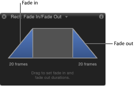
Lets you dissolve into and out of any object. The Fade In/Fade Out behavior affects the opacity of the object to which it is applied, fading from 0 percent opacity to 100 percent opacity at the beginning of the object, and then back to 0 percent opacity at the end. You can eliminate the fade-in or fade-out effect by setting the duration of either to 0 frames.
Note: This behavior is multiplicative. This means that the Fade In and Fade Out parameters are multiplied by the object’s current opacity to produce the resulting level of transparency.
The Fade In/Fade Out behavior is useful for introducing and removing elements you’re animating in a project. For example, you can apply the Fade In/Fade Out behavior to text that moves across the screen to make it fade into existence, and then fade away at the end of its duration.
Note: Fade In/Fade Out behavior cannot be applied to a camera or light.
- End Offset: A slider that lets you offset the end of the behavior’s effect relative to the last frame of its position in the Timeline, in frames. Adjust this parameter to make the behavior stop before the actual end of the behavior in the Timeline. Use this slider to offset the end of the Fade Out effect from the end of the object.
The HUD lets you control the Fade In and Fade Out durations, equivalent to the Fade In Time and Fade Out Time parameters in the Behaviors Inspector. Drag anywhere in the shaded area of the Fade In or the Fade Out ramp to adjust their durations.
Note: Continue dragging beyond the limits of the graphical HUD control to extend the durations of the Fade In or Fade Out.
Grow/Shrink
Use the Grow/Shrink behavior to animate the scale of an object, enlarging or reducing its size over time at a speed defined by the Scale Rate or Scale To parameter. The Grow/Shrink effect begins at the object’s original size at the first frame of the behavior.
Note: The Grow/Shrink behavior cannot be applied to cameras or lights.
Tip: To scale particles over their lifetime, use the Scale Over Life particle behavior. For more information, see Using Particles Behaviors.
Note: The vertical and horizontal growth rates can be set to independent values, for asymmetrical effects.
The Grow/Shrink behavior is a good one to use with high-resolution graphics to zoom into an image, such as a map or photograph. You can also combine this behavior with the Throw or Wind behavior to pan across the image while zooming into it.
The Grow/Shrink behavior can also be used to emphasize or de-emphasize images in your project. You can enlarge objects to make them the center of attention, or shrink an object while introducing another to move the viewer’s eye to the new element.
- Increment: This pop-up menu lets you choose how the behavior’s effect progresses over its duration in the Timeline. There are three options:
- Continuous Rate: This option uses the Scale Rate parameter to grow or shrink the object by a steady number of pixels per second.
- Ramp to Final Value: This option grows or shrinks the object from its original size to the specified percentage plus the original scale in the Scale To parameter. If the behavior is shortened in the Timeline, the Grow/Shrink effect goes faster.
- Natural Scale: Enabled by default, this option uses an exponential curve to allow the animation to progress slowly when the scale values are small and speed up when the values are large. This creates the illusion that the scaling is occurring at a constant speed.
- Scale Rate/Scale To: Depending on the command chosen in the Increment pop-up menu, the Scale Rate or Scale To parameter defines the speed and magnitude of the effect. This parameter can be expanded to reveal X and Y subparameters by clicking the disclosure triangle to the left. This lets you adjust the horizontal or vertical scale independently.
- Curvature: This parameter lets you adjust the acceleration with which this behavior transitions from the original to the final size. Higher Curvature values result in an easing into and out of the effect, where the object slowly starts to change size, and this change gradually speeds up as the behavior continues. Because Curvature is defined by the length of the behavior in the Timeline, minus the End Offset, it does not affect the overall duration of the effect
Note: The Curvature parameter is not available when the Increment parameter is set to Natural Scale.
- End Offset: A slider that lets you offset the end of the behavior’s effect relative to the last frame of its position in the Timeline, in frames. Adjust this parameter to make the behavior stop before the actual end of the behavior in the Timeline. Use this slider to offset the end of the Grow/Shrink effect from the end of the object.
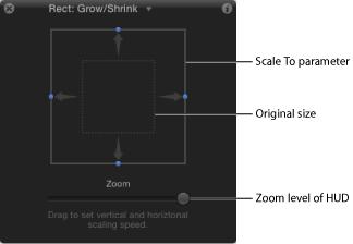
The Grow/Shrink HUD consists of two rectangular regions. The first, a rectangle with a dotted line, represents the original size of the object. The second is a solid rectangle that represents the relative growth rate, and can be resized by dragging any of the borders. Enlarge the box to grow the target object, or reduce the box to shrink it. A slider to the right lets you adjust the scale of the HUD controls, increasing or decreasing the effect the controls have over the object.
Motion Path
The Motion Path behavior lets you create a 2D or 3D motion path for an object to follow. When you first apply the Motion Path behavior, it defaults to an open spline—a straight line defined by two points at the beginning and end of the motion path. You can also choose from preset path shapes, such as a closed spline, loop, rectangle, or wave, or use a shape to define a path. A shape used as the source for a motion path can be animated.
You can modify the motion path in 3D space so an object travels on the path along the path’s X, Y, and Z axes. For more information, see Adjusting a Motion Path in 3D Space.
The first point on the path is the position of the object in the Canvas at the first frame of the behavior. Option-click anywhere on the path to add Bezier points, which allow you to reshape the motion path by creating curves.
Note: To show or hide the motion path, choose Show Overlays from the View pop-up menu in the status bar. (The Animation Path option shows and hides the animation paths of other behaviors.)
When you play the project, the object moves along the assigned path. The speed at which the target object travels is defined by the duration of the behavior. Speed is also affected by the Speed parameter, which lets you modify the object’s velocity—adding acceleration and deceleration at the beginning and end of the behavior, for example. You can also create a custom preset defining how the object travels along the path.
Note: When you switch between the Path Shape options, the Inspector and the HUD display parameters specific to the selected option.
The Motion Path behavior is an easy way to create predictable motion without using the Keyframe Editor. It’s also a great way to create reusable motion paths that you can save in the Library for future use.
When the Motion Path behavior is added to an object, the Adjust Item tool is selected, allowing you to modify the default path in the Canvas by adding points and using the Bezier (or B-Spline) controls attached to each point to adjust each curve. You can also move and resize preset motion path shapes, such as a rectangle or wave, in the Canvas.
- Path Shape: A pop-up menu that lets you define the shape of the path on which the object travels.
- Open Spline: The default shape, a straight path defined by two points at the beginning and end of the path. You can choose to work with Bezier or B-Spline control points. Option-click (or double-click) anywhere on the path to add points.
- Closed Spline: A closed path in which the last point is in the same location as the first point. You can choose to work with Bezier or B-Spline control points. Option-click (or double-click) anywhere on the path to add points.
- Circle: A simplified version of Closed Spline, in which the X radius or Y radius can be adjusted to create a circle or an ellipse. Use the outer control points to resize the circle (or rectangle) motion path’s shape.
- Rectangle: A closed path in which the width and the height can be adjusted to create a square or a rectangle.
- Wave: A wavy path (a sine wave) defined by two points, one at the beginning and one at the end of the path, and controlled by the End Point, Amplitude, Frequency, Phase, and Damping parameters.
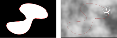
- Geometry: The object travels along the edge of a shape or mask used as the source for the path. In the following figure, the outline of the shape on the left is used as the motion path in the composition shown on the right.
Note: The Path Shape parameters work similarly to text on a path. For more information about working with text on a path, see Working with Text on a Path.
- Shape Type: When Path Shape is set to Open Spline or Closed Spline, this pop-up menu allows you to choose one of two ways to manipulate the shape of the path: Bezier or B-Spline.
- Bezier: Lets you manipulate the keyframe curve manually by dragging the handles.
Note: For more information about creating and adjusting Bezier curves, see Editing Bezier Control Points.
- B-Spline: B-Splines are manipulated using only points—there are no tangent handles. The points themselves do not lie on the surface of the shape. Instead, each B-Spline control point is offset from the shape’s surface, magnetically pulling that section of the shape toward itself to create a curve. B-Splines are extremely smooth—by default, there are no sharp angles in B-Spline shapes, although you can create sharper curves, if necessary.
Note: For more information about working with B-Spline curves, see Editing B-Spline Control Points.
- Radius: When Circle is the defined path shape, this slider allows you to change the size of the circular path. Click the disclosure triangle to individually adjust the X radius and Y radius.
Note: When the Motion Path behavior is selected, you can also use the onscreen control points to resize the circle. Press Shift to resize the X and Y radii uniformly.
- Size: When Rectangle is the defined path shape, this slider allows you to change the size of the rectangular path. Click the disclosure triangle to individually adjust the X scale and Y scale.
Note: When the Motion Path behavior is selected, you can also use the onscreen control points to resize the rectangle. Press Shift to resize the X and Y scales uniformly.
- End Points: When Wave is the defined path shape, this control sets the location of two default points on the wave’s path. The end points can also be adjusted using the wave’s onscreen controls (active by default when the Motion Path behavior is selected). Moving the left end point moves the entire path; moving the right end point lengthens, shortens, or angles the path.
- Phase: When Wave is the defined path shape, this dial defines the degrees of the offset of the waves from the start and end points of the path. When set to 0 degrees (default), the wave begins and ends at half the distance from the highest point to the lowest point in the wave. When set to 90 degrees, the wave begins and ends at the highest point in the wave. When set to –90 degrees, the wave begins at the lowest point in the wave. When set to 180 degrees, the waves are the same as 0 degrees, but inverted.
- Damping: When Wave is the defined path shape, this slider progressively diminishes the oscillation of the wave. Positive damping values diminish the wave forward (from left to right); negative values diminish the wave backward (from right to left). The following illustration shows positive damping applied to the wave motion path.
- Attach to Shape: When Geometry is the defined path shape, this checkbox, when activated, forces the motion path to follow the source shape at its original location. When disabled, the motion path can exist in a location other than its source shape.
Note: When Attach to Shape is on, you cannot move the object to another location.
Tip: To align the rotation of an object to match all changes made to its position along an animation path, apply the Snap Alignment to Motion behavior. For more information, see Snap Alignment to Motion.
- Direction: A pop-up menu that defines the object’s direction over the path. There are two options:
- Forward: The object moves in a forward direction along the path (from the start point to the end point, depending upon the Offset parameter).
- Reverse: The object moves in a backward direction along the path (from the end point to the start point, depending upon the Offset parameter).
Note: The Offset parameter is available when Path Shape is set to Circle or Rectangle.
- Speed: A pop-up menu that defines the object’s velocity from the first to the last point in the motion path. There are eight choices:
- Constant: The object moves at a steady speed from the first to the last point on the motion path.
- Ease In: The object starts at a slow speed, then reaches and maintains a steady speed through the last point on the motion path.
- Ease Out: The object starts at a steady speed, then slows down as it gradually decelerates to a stop at the last point of the motion path.
- Ease Both: The object slowly accelerates from the first point on the motion path, and then slows down as it gradually decelerates to a stop at the last point of the motion path.
- Accelerate: The object moves along the path with increasing speed.
- Decelerate: The object moves along the path with decreasing speed.
- Natural: The speed in which the object moves over the path is determined by the shape of the path. For example, if the path is a U-shape curve, the object moves faster as it moves toward the low point of the U and slower as it moves up the edges.
- Custom: Custom allows you to define the movement of the object along its path by setting keyframes for the object’s speed from 0 to 100 percent. In other words, you determine the position of the object along the path in time.
- Custom Speed: This parameter becomes available when Speed is set to Custom. You can modify the Custom Speed velocity curve in the Keyframe Editor. You can keyframe custom values to make an object, for example, travel forward to a specific percentage of the path, then backward, then forward, and so on before it reaches the end of the animation.
- Apply Speed: When the Loops parameter is set to a value greater than 1, this pop-up menu determines how the Speed parameter (velocity) is applied over the duration of the behavior.
Note: Loops must be set to a value greater than 1 for the Apply Speed parameter to have any effect.
- Once Per Loop: The velocity, as defined by the Speed parameter, is applied to each cycle. For example, if Loops is set to 3 and Speed is set to Accelerate, the object accelerates each time it travels over the path. The speed is applied to the entire duration, ignoring the Loops setting.
- Over Entire Duration: The velocity, as defined by the Speed parameter, is applied one time over the duration of the behavior. For example, if Loops is set to 3 and Speed is set to Accelerate, the object accelerates the first time it travels over the path, but not the second and third time.
- Control Points: This parameter becomes available when the path shape is Open Spline or Closed Spline. Click the disclosure triangle to display the Position parameters for the motion path control points. The first value field is X, the second value field is Y, and the third value field is Z.
Note: You cannot apply Parameter behaviors to the control points.
In the HUD, the following controls are always available: Path Shape, Shape Type, Direction, Speed, Custom Speed, Apply Speed (sets the number of times the object travels the path over the object’s duration), and End Condition. Other parameters become available depending on what is selected from the Path Shape parameter.
Motion Path Tasks
The following tasks show you how to customize the Motion Path behavior.
Distancing the Object from the Motion Path
By default, the object is locked to the motion path by its anchor point.
Select the Anchor Point tool from the toolbar and move the anchor point in the Canvas.
For more information on using the Anchor Point tool, see Using the Anchor Point Tool.
Note: A separate Offset parameter allows you to offset the starting location of the object on the motion path (but does not offset the object from the path).
Moving the Object and Its Motion Path
Moving an object moves the object’s related motion path.
Select the object (not the Motion Path behavior), and move the object in the Canvas.
Using Geometry for a Motion Path Shape
The following section describes how to use geometry as the source for a motion path shape. You can use a shape that is animated with behaviors or keyframes as the source for a motion path. This includes animated transforms (a shape changing its location in the Canvas) and animated control points (a shape changing its shape due to keyframed control points).
Import (or draw) the shape to use as the path source.
Choose Geometry from the Path Shape pop-up menu.
The Shape Source well appears in the Inspector and HUD.
From the Layers list, drag the shape to the Shape Source well.
When the pointer becomes a curved arrow, release the mouse button.
A thumbnail of the shape appears in the well and the shape is used as the source shape for the motion path.
Note: You might want to disable the source shape in the Layers list so the source shape is not visible in your project.
Choose the object to use as the motion path’s shape source from the To pop-up menu (located next to the Shape Source image well).
Note: To align the rotation of the object to the shape of its motion path, you can apply the Snap Alignment to Motion behavior (in the Basic Motion behaviors subcategory).
In the Inspector or HUD, choose Custom from the Speed pop-up menu.
The Custom Speed parameter becomes available. By default, a keyframe is set at the first and last points of the behavior to create an animation of 0 percent to 100 percent, where at 0 the object is at the beginning of the path, and at 100 the object is at the end of the path. This is the same velocity used with the Constant preset.
Enable Record (press A).
Note: When Record is enabled, all keyframeable parameter value fields are tinted. This is to remind you that any value change entered in this state creates a keyframe.
Move the playhead to the position where you want to create a keyframe, then enter a value in the Custom Speed field.
For example, a value of 90 moves the object 90 percent of the way through the motion path.
Continue moving the playhead and adding keyframes to obtain the result you want.
Note: If you change the Speed parameter to a preset (such as Constant) after creating a custom speed, the custom velocity channel is ignored but remains intact.
Adjusting a Motion Path in 3D Space
You can adjust a motion path in 3D space. The easiest way to modify a motion path in 3D space is to add a camera to your project and manipulate the path in a modified camera view.
If there is no camera in your project, add a camera by doing one of the following:
Click the New Camera button in the toolbar.
Choose Object > New Camera (or press Command-Option-C).
Note: If none of your project groups are set to 3D, a dialog appears asking if you want to switch your 2D groups to 3D groups. Click Switch to 3D to allow the camera to affect the groups.
Do one of the following:
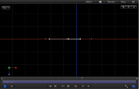
Choose a camera view from the Camera pop-up menu in the upper-left corner of the Canvas (the default option is Active Camera). This example uses the Top view.
With the Active Camera (or other) view selected, use the Orbit tool (the center tool in 3D View tools in the upper-right corner of the Canvas) to rotate the camera.
Note: If you use the 3D View tools with any camera selected, you are moving the camera, not just changing the camera view.
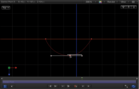
Depending on the camera view, the object on the path might not be visible. For example, if the object has not been rotated in X or Y space and you are working in Top view, the camera is looking down perpendicularly (on the Y axis) on the object. The motion path and its points are still visible (as long as the Motion Path behavior is selected).
In the following image, the motion path appears flat when viewed from above—the affected object only moves in X and Y space.
Drag a control point up or down to adjust the object in Z space.
In the following image, the path is no longer flat—the affected object moves in X, Y, and Z space.
Note: The motion path onscreen controls are available for all camera views.
To enter specific values for the control point locations, click the Control Points disclosure triangle in the Motion Path behavior parameters. The first value field is X, the second value field is Y, and the third value field is Z.
To reset the camera view, do one of the following:
Double-click the 3D View tool that you previously adjusted. For example, if you dragged the Orbit tool to rotate the current camera, double-click the Orbit tool to reset the camera.
If you chose (and/or modified) a default camera view (such as Top, Right, Left, and so on), choose Active Camera from the Camera menu, or choose View > 3D View > Active Camera.
With the camera selected, click the reset button in the Properties Inspector.
Move
The Move behavior places a point in the Canvas that creates a specific location for an object or group to move toward or away from in a straight line.
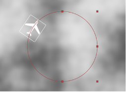
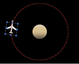
In the following illustration, an Orbit Around behavior is applied to the airplane shape.
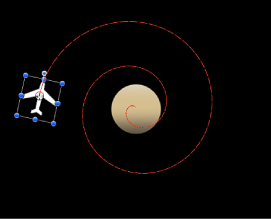
In the next illustration, a Move behavior is added to the airplane shape. The destination point of the Move path is positioned in the center of the circle. While the airplane circles around (obeying the Orbit Around behavior), it is also drawn to the center of the target (obeying the Move behavior), creating a spiraling motion path.
Tip: The Move behavior is an ideal tool when working in 3D mode, as it allows you to simulate camera movements without using a camera. For example, when applied to a group that contains objects offset in Z space, you can create a dolly-like move.
- Position: Value fields that allow you to define the X, Y, and Z position of the target point. The target (the end of the Move path) is placed at the center of the Canvas by default.
Note: The Move behavior and the Adjust Item tool must be selected to move the target corresponding to the Position parameter. Use the Select/Transform tool to move the object.
- Speed: A pop-up menu that defines the object’s velocity from its position in the Canvas to the position of the target. There are six choices:
- Constant: The object moves at a steady speed from its position toward the target.
- Ease In: The object starts at a slow speed, then reaches and maintains a steady speed toward the target.
- Ease Out: The object starts at a steady speed, then slows down as it gradually decelerates to a stop when it reaches the target.
- Ease Both: The object slowly accelerates and then slows down as it gradually decelerates to a stop when it reaches the target.
- Accelerate: The object moves toward the target with increasing speed.
- Decelerate: The object moves toward the target with decreasing speed.
Note: To move the object more slowly toward its target, extend the duration of the Move To behavior in the Timeline or mini-Timeline. To move the object faster, shorten the duration of the behavior.
The HUD has a slider that sets the influence amount (Strength), a Direction pop-up menu that defines whether the object moves toward the null point or away from the point, and a Speed pop-up menu that allows you to define the object’s velocity.
Point At
When the Point At behavior is applied to an object or group, you can specify a target point for the affected object to turn toward.
Tip: Use the Point To behavior with the Move To behavior to created animated objects that not only move toward a point (or each other), but that turn in the direction of the target.
- Transition: This slider determines how long it takes for the object to go from its starting orientation to pointing at the center of the target object. This parameter is useful when the object is pointing at a moving target object.
If Transition is set to 50% in a 300-frame project, and the target object is not moving, the point-at object takes 150 frames to point at (or orient to) the center of the target object and then stops moving for the duration of the behavior. If Transition is set to 100%, the point-at object takes the full 300 frames to point at the target object. If the Point At behavior’s duration is 100 frames, and Transition is set to 50%, the point-at object takes 50 frames to orient to the target object.
If Transition is set to 50% in a 300-frame project, and the target object is animated, the point-at object takes 150 frames to point at (or orient to) the center of the target object and then continues following the animated target object for the duration of the behavior. If Transition is set to 100%, the point-at object takes the full 300 frames to point at the target object.
- Speed: A pop-up menu that defines the object’s velocity from its position in the Canvas to the position of the target. There are six choices:
- Constant: The object moves at a steady speed from its position toward the target.
- Ease In: The object starts at a slow speed, then reaches and maintains a steady speed toward the target.
- Ease Out: The object starts at a steady speed, then slows down as it gradually decelerates to a stop when it reaches the target.
- Ease Both: The object slowly accelerates and then slows down as it gradually decelerates to a stop when it reaches the target.
- Accelerate: The object moves toward the target with increasing speed.
- Decelerate: The object moves toward the target with decreasing speed.
The HUD has an Object well, a Transition slider, a Speed pop-up menu that allows you to define the object’s velocity, an Axis pop-up menu to choose which axis should point at the target after the movement is complete, and an Invert Axis checkbox.
Snap Alignment to Motion
This behavior aligns the rotation of an object to match all changes made to its position along an animation path. This behavior is meant to be combined with behaviors that animate the position of an object, or with a keyframed animation path you create yourself.
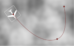
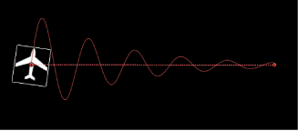
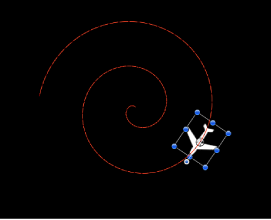
In the following example, a graphic of an airplane is shown travelling a spiral motion path. On its own, the orientation of the graphic doesn’t change, because only the Position parameter is affected.
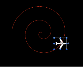
If you add the Snap Alignment to Motion behavior to the airplane graphic, the Rotation parameter is affected so the graphic points in the direction of motion, without the need for additional keyframing.
- End Offset: A slider that allows you to offset the end of the behavior’s effect relative to the last frame of its position in the Timeline, in frames. For example, if End Offset is set to 60, the object actively snaps to the direction of the path until 60 frames before the end of behavior in the Timeline.
The HUD has a pop-up menu to control the axis around which the object is rotated, a pop-up menu to control the axis used to adjust the object’s alignment, and a checkbox to let you invert the axis.
Spin
Apply the Spin behavior to animate the rotation of an object, spinning it around a single axis. Using the Custom axis controls, the rotation does not have to occur on a principle axis (X, Y, or Z). If you trim the end of the Spin behavior to be shorter than the duration of the object to which it is applied, it remains at the angle of the last frame of the behavior, as long as there are no other behaviors or keyframes affecting that object’s Rotation parameter.
Uses for Spin are fairly obvious, but another way to use the Spin behavior is with objects that have an off-center anchor point. Because objects rotate around the anchor point, if you change an object’s anchor point before you apply a Spin behavior to it, you can change the look of the motion you create. For more information on changing an object’s anchor point, see Using the Anchor Point Tool.
Note: Although the Spin behavior appears in the Basic Motion category, Spin is treated as a Simulation behavior in Motion’s order of operations. For more information, see Behavior Order of Operations.
- Affect Subobjects: This parameter appears when Spin is applied to an object that contains multiple objects, such as a group, particle emitter, or text. When this checkbox is selected, each object in the layer or group rotates as an individual object. When this checkbox is deselected, the entire layer or group spins.
- Spin Rate/Spin To: A dial controlling the speed at which the object spins. When Increment is set to Continuous Rate, the Spin Rate defines a continuous rate of spin in degrees per second. When Increment is set to Ramp to Final Value, Spin To defines a number of degrees to spin over that object’s duration. Negative values result in clockwise motion, while positive values result in counterclockwise motion.
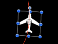
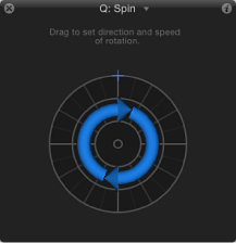
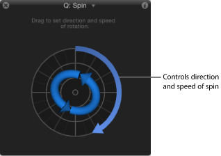
- Axis: A pop-up menu that allows you to choose whether the object spins about the X, Y, or Z axis. You can also choose Custom, which yields additional Longitude and Latitude parameters. The following illustration shows the Spin behavior’s HUD control set to the Z axis.
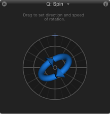
When Axis is set to Custom, additional Longitude and Latitude parameters become available. These parameters allow the object to spin at an angle (not locked to the X, Y, or Z axes). If you’re working on an object in a 3D group, you can also drag the axis control in any direction to simultaneously modify the longitude and latitude of spin, as seen in the following illustration.
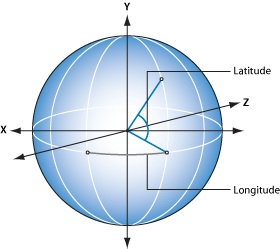
The following image shows how longitude and latitude relate to the Spin HUD control.
The Spin behavior’s HUD controls include an outer ring and an inner control. Drag along the edge of the outer ring to manipulate an arrow that indicates the direction and speed the object spins. Adjust the length of the arrow to change the speed at which the spinning occurs—drag around multiple times to increase the rate of the spin.
The inner arrow controls the axis about which the object or group spins. When you drag the inner controls, a globe control becomes available that allows you to adjust the object’s spin in degrees longitude and latitude.
Note: You can spin the arrow around the ring multiple times to rotate the object more quickly.
Throw
The Throw behavior is the simplest way of setting an object in motion. Controls let you adjust the speed and direction of a single force that’s exerted on the object at the first frame of the behavior. After this initial force is applied, the object continues drifting in a straight line at the same speed, for the duration of the Throw behavior.
A simple example of using the Throw behavior is to send a series of offscreen objects moving across the screen. When used in conjunction with other behaviors such as Grow/Shrink and Fade In/Fade Out, you can create sophisticated moving elements without keyframing a single parameter.
The Throw behavior is also useful when you’re moving an object through a simulation. For example, you might move the object past other objects that have Attractor or Repel behaviors applied to them. Because the Throw behavior only applies a single force to move the target object at the initial frame of the behavior, any other behaviors that interact with the target object have potentially greater influence over its motion.
Important: The Throw behavior does not apply a continuous force, nor can you create changes in direction or speed, because Throw cannot be keyframed. To create keyframed changes in direction or speed, use the Wind behavior. To create a more complex animation path, use the Motion Path behavior.
- Affect Subobjects: This parameter appears when Throw is applied to an object that contains multiple objects, such as a group, particle emitter, or text. When this checkbox is selected, each object within a parent object moves as an individual object. When this checkbox is deselected, the entire layer or group moves as a whole.
- Increment: This pop-up menu lets you choose how the behavior’s effect progresses over its duration in the Timeline. There are two choices:
- Continuous Rate: Sets the speed of the object at a steady number of pixels per second, specified in the Throw Velocity parameter.
Note: If the Canvas is displaying a nonsquare pixel image, the vertical rate is in pixels per second, and the horizontal rate is the perceptual equivalent.
- Ramp to Final Value: Moves the object from its original position to the specified distance (in pixels) in the Throw Distance parameter.
- Throw Velocity/Throw Distance: When the Increment pop-up menu is set to Continuous Rate, the Throw Velocity parameter appears, which lets you set a continuous speed for the object to move in X, Y, or Z space. When the Increment pop-up menu is set to Ramp to Final Value, the Throw Distance parameter appears, which sets a total distance (in pixels) for the object to travel in X, Y, and Z space over its duration. The slider is limited to 100 pixels. Use the value field to enter values greater than 100.
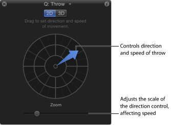
The 2D HUD lets you specify the direction and speed of the Throw behavior by dragging an arrow in a circular region. The direction of the arrow defines the direction of movement in X and Y space, and the length of the arrow defines speed (velocity). A slider to the right lets you adjust the scale of the HUD control, increasing or decreasing the effect the direction/speed control has over the object.
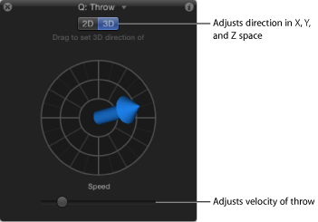
When you click the 3D button, additional 3D controls become available. The center arrow now defines the direction the object is thrown in 3D space (X, Y, and Z axes). The Speed slider (on the left side of the HUD) lets you increase or decrease the velocity of the thrown object.
In the 2D and 3D Throw HUDs, press the Shift key while dragging the arrow to constrain it to 45 degree angles. In the 2D HUD, press the Command key to change the arrow’s direction without affecting its length.
Note: The maximum speed you can define with the HUD is not the maximum possible speed. Higher values can be entered into the Throw Velocity/Throw Distance parameter in the Behaviors Inspector.