Text Layout-Related Tasks
These tasks are useful when editing text Layout parameters, which include working with text on a path and creating a type-on effect.
Creating Text on a Path
To place text on a path, you create a text object, set the Layout Method to Path, then use the Path Options parameters to modify the text on a path.
Select the text to place on a path.
In the Layout pane of the Text Inspector, choose Path from the Layout Method pop-up menu.
The Path Options parameters become available.
Select the Text tool (or press T) and click the text in the Canvas.
Important: Step 3 is important—the Text tool must be selected to view or edit the text path.
The path appears below the text. The default path shape is set to Open Spline and contains three control points.
Working with Text on a Path
A Spline text path can be manipulated to move through 3D space. You can change the shape of a text path, add or remove control points, and animate the text along the path. Text on a path can still be edited—you can change text characters or fonts, tracking, kerning, and so on. Text Style parameters can also be modified for text on a path.
Using Behaviors with Text on a Path
Text, Simulation, Parameter, and Basic Motion behaviors can be applied to text on a path. This allows for the creation of clever and complex animation.
For more information on using Simulation and Parameter behaviors, see Using Other Behaviors with Text.
Modifying the Path Shape
The Text tool must be selected to view and edit the text path. Use the following procedures to modify the shape of the path.
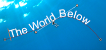
With the Text tool selected, drag a path control point to change the shape of the path.
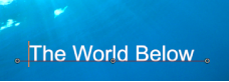
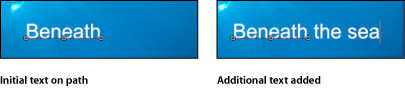
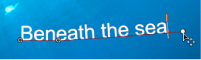
When additional text characters are added to text that is on a path, the default path may appear too short. In the following images, the first image shows the original text placed on a path. The second image shows additional text. In the second image with the added text characters, the path is shorter than the text.
With the Text tool selected, drag the last control point toward the end of the text.
Tip: When dragging, press Shift to constrain the path to a straight line.
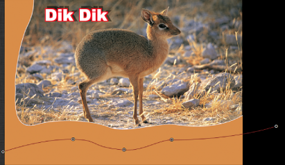
After you extend a path, add control points for extra control over the shape of the path.
Option-click or double-click the path to add a control point.
Note: Control points can only be added to Open Spline or Closed Spline paths.
To remove a control point, select the point, then press Delete. You can also Control-click the point, then choose Delete Point from the shortcut menu.
To create a linear point, Control-click the point, then choose Linear from the shortcut menu.
To create a smooth (Bezier) point, Control-click the point, then choose Smooth from the shortcut menu.
Note: When Path Type is set to B-Spline, the Very Smooth option becomes available in the shortcut menu.
To lock a point, Control-click the point, then choose Lock Point from the shortcut menu. A locked point cannot be edited.
To unlock a point, Control-click the point, then choose select Unlock Point from the shortcut menu.
Important: Text paths are modified in the same way as shape control points. For complete information, see Using Shapes, Masks, and Paint Strokes.
Note: Clicking any path control point and holding down the mouse button displays the point number (based on the order the points are drawn on the path) and X, Y, and Z coordinates in the status bar. Path control points are also listed by number in the Layout pane of the Text Inspector.
If there is no camera in the project, add a camera by doing one of the following:
Click the Add Camera button in the toolbar.
Choose Object > New Camera (or press Command-Option-C).
Note: If none of your project groups is set to 3D, a dialog appears asking you if you want to switch your 2D groups to 3D groups. Click Switch to 3D to allow the camera to affect the groups.
To change the default camera view (Active Camera) to Top, do one of the following:
Click “Active Camera” in the upper-left corner of the Canvas to open the Camera menu, then choose Top.
Choose View > 3D View > Top.
The text is no longer visible because the camera is now looking down perpendicularly (on the Y axis) at the text on a path. The text path and its points are still visible. (The yellow wireframe camera icon in the Canvas represents the Active Camera you added in step 1.)
Note: The text path onscreen controls are available for all camera views. This example uses the Top view.
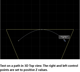
With the Text tool selected, drag a control point to adjust the text path in X, Y, or Z space.
Note: Manipulating text on a path in 3D space only works when Path Shape is set to Open Spline or Closed Spline.
Tip: If the path selection disappears, reselect the text layer in the Layers list.
Note: To enter values for the control point locations for Open Spline or Closed Spline, click the Control Points disclosure triangle in the Path Options group of the Layout pane. The first value field is X, the second value field is Y, and the third value field is Z.
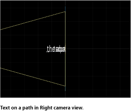
To change the camera view, choose another camera view from the Camera menu in the upper-left corner of the Canvas.
To reset the camera view, do one of the following:
Choose Active Camera from the Camera menu.
Choose View > 3D View > Active.
Tip: When working with text in a 3D project (especially text that moves close to the camera), before exporting, set the Render Quality to Best (choose View > Quality > Best). Best mode dramatically slows project performance and interactivity, so you might want to set the Render Quality to Normal while working. You can also set the Render Quality on export in the Export Options dialog: Choose Export, click Options, then choose Best from the Render Quality pop-up menu. To customize an export, deselect the “Use current project and canvas settings” checkbox.
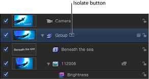
Isolating a Group or Object to Work with Text on a 3D Path
When working with text on a 3D path, text can be difficult to read depending on its orientation and distance from the camera. To edit the text, you can snap the text object to its original face-forward orientation using the Isolate button in the Layers list (or Timeline) or the Isolate command in the Object menu.
Note: The Isolate command is only available for selected objects.
In the Layers list (or Timeline), click the Isolate button.
Control-click the layer or group, then choose Isolate from the shortcut menu.
Choose Object > Isolate.
Click the Isolate button again to return to your previous view.
Note: Clicking a camera’s Isolate button activates that camera’s view.
Using Geometry for a Path Source
The following section describes how to use geometry as the source for a text path.
Import (or draw) the shape you want to use as the path source.
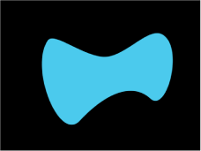
Set the text Layout Method to path, then choose Geometry from the Path Shape pop-up menu.
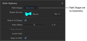
The Shape Source well appears in the Inspector.
From the Layers list, drag the shape to the Shape Source well.
When the pointer becomes a curved arrow, release the mouse button.
A thumbnail of the shape appears in the well and the shape is used as the source shape for the text path.
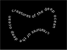
Note: You might want to disable the source shape in the Layers list so it is not visible in your project.
Click the To pop-up menu (located next to the Shape Source image well) and select the object to use as the text path’s shape source. All shapes or masks in the project appear in the list.
Animating Text on a Path
Text can be animated to move across the text path.
Create the path for the text to travel along.
Go to the frame where you want to begin the animation, and enable Record (press A).
Note: Using shortcut keys while in text-editing mode can add characters to your text.
In the Layout pane, adjust the Path Offset slider or value slider to the amount you want to move the text on the path.
A keyframe is added to the Path Offset parameter.
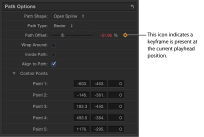
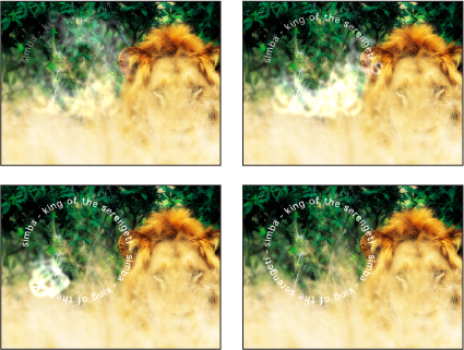
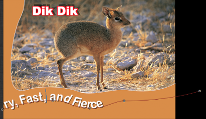
A positive value moves the text toward the right, and a negative value moves the text toward the left. You can enter values greater than 100% or less than 0% in the value slider. A value greater than 100% moves the text completely off the path to the right; a value less than 0% moves the text off the path to the left. In the following image, the Path Offset is set to 105%, so the text is completely off the right end of the text path.
Go to the frame where you want to place the next keyframe.
Adjust the Path Offset slider or value slider to reposition the text on the path.
Play the project to see the text travel along the text path.
Disable Record.