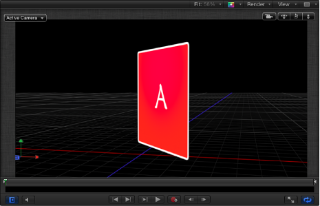
3D Workspace and Views
In a 3D workspace, everything is seen from the viewpoint of a camera. The default views presented in the 3D workspace are reference cameras that can be used and manipulated to help place and animate objects but are not used for rendering output. To render from one of the camera views, you must create a scene camera. For more information on cameras, see Cameras.
Views
There are several view layouts, with each layout consisting of an arrangement of viewports. Each viewport displays the scene from the point of view of a camera. Reference camera views have a specific default position and orientation.
There are two types of reference cameras:
Orthographic
Perspective
An orthographic camera views the scene by looking straight down one of the world axes: X, Y, or Z. The default orthographic cameras do not appear in the Layers list, Timeline, or Canvas. The Front and Back cameras look straight down the Z axis. The Top and Bottom cameras look straight down the Y axis. The Left and Right cameras look straight down the X axis.
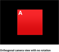
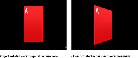
Orthographic cameras do not show perspective. Perspective cameras—and scene cameras that you add to a project—distort the view the way a real-world camera would.
To access camera views and camera controls, add a scene camera to your project.
Choose Object > New Camera (or press Command-Option-C).
A camera object is added to the Layers list, the Timeline, and the Canvas (represented there by a wireframe icon). The 3D Transform tool in the toolbar becomes active, the Camera HUD appears (if it isn’t visible, press F7), and the Camera pane in the Inspector becomes available.
If you add a camera to a project that contains no existing 3D groups, the following dialog appears:
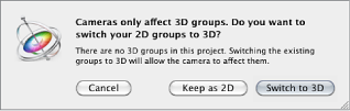
Click Keep as 2D or Switch to 3D.
After you add a camera to a project, the Camera menu becomes available in the upper-left corner of the Canvas.
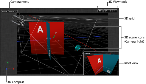
3D Canvas Overlays
There are six 3D overlays that can appear in the Canvas: the Camera pop-up menu, the 3D View tools, the Inset view, the 3D grid, the 3D Compass, and the 3D scene icons. You can turn the display of overlays on or off.
Choose View > 3D Overlays, then choose the type of 3D overlay to show or hide.
From the View pop-up menu in the status bar, choose the type of 3D overlay to show or hide.
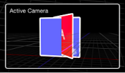
Camera Menu
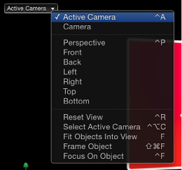
The Camera pop-up menu, located in the upper-left corner of the Canvas, lists the active camera view. Choose from a list of reference cameras and scene cameras. The menu also contains several view-related commands.
The Camera menu is divided into three sections:
The top section allows you to select the active camera as well as any other scene cameras you have added to the project. If a scene contains more than one camera, the topmost camera in the Layers list at the current frame in the Timeline is the active camera. For more information on scene cameras, see Cameras.
The middle section allows you to select a default reference camera: Perspective, Front, Back, Left, Right, Top, Bottom.
The bottom section allows access to five frequently used commands: Reset View, Select Active Camera, Fit Objects Into View, Frame Objects, and Focus on Object. For details on these commands, see the 3D View section in View Menu.
3D View Tools
The 3D View tools control reference and scene cameras.
The scene camera indicator appears at the left of the 3D View tools when a scene camera is the active camera.
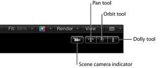
There are three 3D View tools:
- Pan: Drag in this box to move the camera along the X and Y axes relative to the current view.
- Orbit: Drag in this box to orbit the camera around the selected scene object. If nothing is selected, the camera orbits around its focal plane. For more information on the camera focal plane, see Camera Controls. Orbit can affect X, Y, and Z Position values, as well as X and Y Rotation values.
Note: If you use the orbit control to change an orthogonal reference camera, an asterisk appears next to the view’s name in the Camera menu, indicating that the view is no longer a true orthogonal view.
- Dolly: Drag in this box to dolly the camera, moving it along the Z axis relative to the current view.
Tip: Double-clicking a 3D View tool resets all parameters that can be affected by the tool.
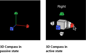
3D Compass
Located in the lower-left corner of the Canvas, the 3D Compass acts as an orientation and shortcut device. It has active and passive states, depending on whether the pointer is positioned over it. In its passive state, it displays the orientation of the three world axes (X, Y, and Z). In its active state, the compass presents color-coded shortcuts to activate the reference (orthogonal and perspective) cameras.
Position the pointer over the compass.
The compass changes to its active state, displaying a labeled icon for each reference camera view.
Click the icon representing the camera to activate.
The view in the Canvas updates to the selected reference camera view.
Position the pointer over the 3D Compass.
The compass changes to its active state.
Control-click the 3D Compass, then choose a scene camera from the shortcut menu.
The view in the Canvas changes to the selected scene camera view.
Note: You can also choose a reference camera view from the 3D Compass shortcut menu.
Inset View
When you move an object in a 3D project, an Inset view appears in the lower-right corner of the Canvas, showing the scene from a different camera’s point of view. If you are viewing the scene through the active camera, the Inset view shows the Perspective camera’s point of view. If you are viewing the scene through any other camera, the Inset view shows the active camera. Use the Inset view to see the results of changes that you make in orthogonal views.
Use Motion Preferences to set the Inset view’s size and when it appears in the Canvas. For more information on Inset view properties, see 3D Pane.
3D Grid
The 3D grid shows the ground plane of the 3D world. The ground plane is, as the name states, a plane attached to the ground of the scene, where Y equals 0. The ground plane represents the dividing line between up and down, that is, between positive Y values and negative Y values. It is centered on 0, 0, 0.
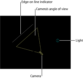
3D Scene Icons
3D scene icons are the onscreen representations of cameras, lights, and edge-on lines. An edge-on line is drawn when an object’s edge faces the camera—which normally results in an invisible object. This allows you to select objects that would otherwise be invisible.
Note: No 3D scene icons appear in exported images or movie clips.
Tip: Double-click a camera scene icon to select it and change the current view to that camera.
Viewport Layouts
Motion allows you to have multiple viewport windows active at the same time in the Canvas to help animate and position objects in 3D space. A pop-up menu, located in the status bar just above the 3D View tools, lets you choose from seven viewport layouts.
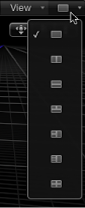
Each layout is represented by an icon in the pop-up menu:
- Single: The default value, displays a single viewport window in the Canvas.
- Two-up, side by side: Displays two viewport windows in the Canvas, one next to the other.
- Two-up, top and bottom: Displays two viewport windows in the Canvas, one on top of the other.
- Three-up, large window below: Displays three viewport windows, two next to each other on top and a larger window below.
- Three-up, large window right: Displays three viewport windows, two stacked on the left side and a larger window spanning the right side.
- Four-up, large window right: Displays four viewport windows, three stacked on the left side and one larger window on the right side.
- Four-up: Displays four viewport windows, all the same size.
Choose a layout from the pop-up menu at the far-right side of the status bar.
The Canvas displays the layout you choose.
When working with multiple viewports, the last view you clicked in is the active view. The active viewport is indicated by a yellow border. Only the active viewport displays onscreen controls.
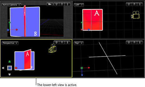
Note: The active viewport in the Canvas is not the same as the Active Camera. For more information, see Active Camera.