You can integrate graphics and other elements into a 360° project. Elements are added to 360° projects in the same way as in normal projects.
Add your text, shape, particle emitter, or other object to a 3D Group in the Layers list.
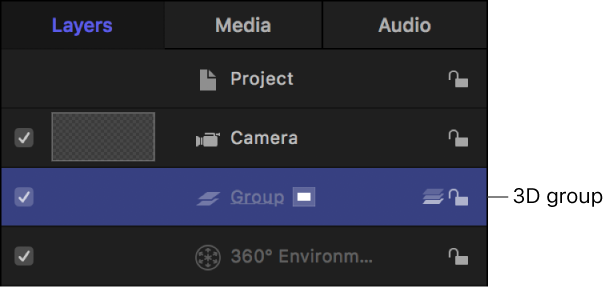
The object is added to the scene. As you navigate the 360° scene, the layer floats at the origin (where X = 0, Y = 0, and Z = 0) in 3D space.
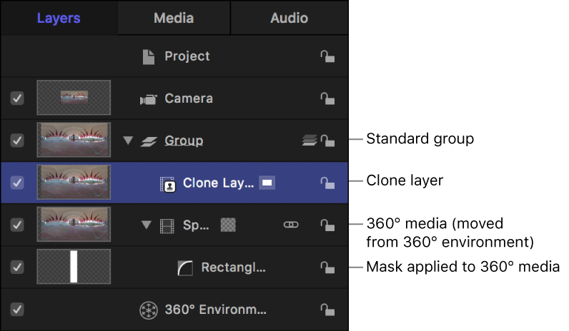
You can’t add masks directly to 360° footage in a 360° environment. However, you can move the 360° footage to a 3D group, mask and clone the footage, then move the clone layer back to the 360° environment. This lets you to draw and adjust the mask in a standard view rather than in a distorted, spherical view.
In the Layers list, drag the 360° media to a standard 3D group.
In the canvas toolbar, click the Mask tools pop-up menu, then choose a mask tool from the list.
In the canvas, draw a mask over the 360° layer.
Tip: For a larger drawing area, you may want to change the canvas layout to a single viewport and change the camera view while working on your mask.
For more information on working with masks, see Shapes, masks, and paint strokes overview.
Select the 360° layer with the applied mask, then choose Object > Make Clone Layer (or press K).
A clone layer is created and appears in the canvas on top of the original layer. Any further adjustments you make to the mask will be applied to the clone layer.
For more information, see Clone a layer.
In the Layers list, deselect the checkbox of the 360° layer with the applied mask.
Make sure you don’t deselect the checkbox of the mask layer.
Drag the clone layer into the 360° environment.
As you navigate the 360° media, the mask is integrated into the scene.
After you’ve moved the cloned 360° layer into the 360° environment, you may need to make further adjustments to the mask.
In the Layers list, select the mask layer, then make adjustments.
The mask adjustments propagate to the clone layer in the 360° environment.
Tip: It may be useful to isolate the layer you’re masking. When a layer is isolated, the layer is set to its default orientation and all other layers are hidden. For more information, see Mask a layer in a 3D project.
Non-360° image layers such as text or logos must be contained in a 360° environment for blend modes to operate correctly. When you import an equirectangular image into a 360° project, the image is automatically added to the 360° environment.
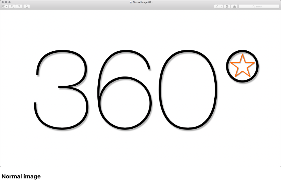
You can create equirectangular images in Motion by importing a normal image into a 360° project, then exporting the image.
Create a new 360° project, then click Import.
In the dialog that appears, navigate to and select a still image, then click Import.
The image is added to the 3D group.
Make adjustments to the image, then choose Share > Save Current Frame.
The message “360° metadata is not supported by the Still Image format” appears in the dialog. You can disregard this message.
Click Next, enter a name and save location for the exported file, then click Save.
The image is saved with the equirectangular projection “baked in” and with the correct aspect ratio (2:1).
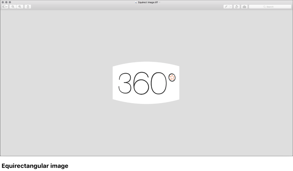
When you import the equirectangular still image back into your 360° project, Motion adds it directly to the 360° environment. You can now apply blend modes to the image.
You can export a 360° equirectangular video with a single field of view for watching on traditional display devices.
In a normal project, click Import.
In the dialog that appears, navigate to and select your 360° video, then click Import.
The video is added to a group.
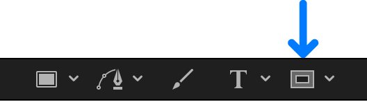
Click Add Object in the toolbar, then choose 360° Environment.
A new 360° environment is added to the project.
In the Layers list, drag the imported 360° video to the 360° environment.
To select the field of view you want to export, do one of the following:
Click Add Object in the toolbar, choose Camera, then adjust the camera’s Angle of View in the Camera Inspector or the camera’s Transform parameters in the Properties Inspector.
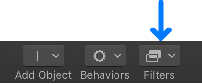
Select the 360° media in the Layers list, click Filters in the toolbar and choose 360° > 360° Reorient, then adjust the filter’s parameters in the Filters Inspector.
Note: You can also use a combination of a camera and a Reorient filter to select the field of view you want to export.
For details about the 360° Reorient filter parameters, see Change the default orientation of 360° media.
After you’ve framed the area of the image you want to export, choose Share, select an export option, then follow the onscreen instructions. For more information, see Share Motion projects overview.
A normal projection video with a single field of view is exported.
You can integrate particles, replicators, and other objects into a 360° scene. Keep in mind that the equirectangular projection is navigable by the viewer at all times.
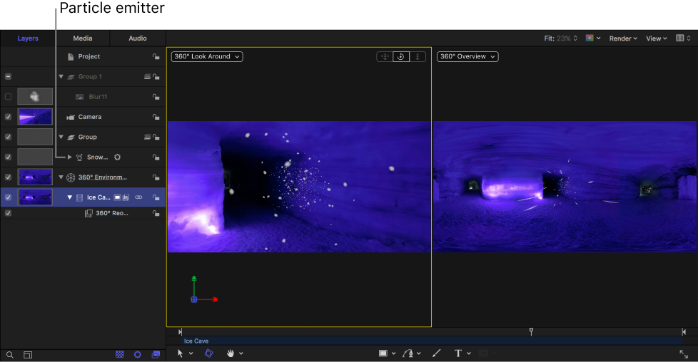
This example demonstrates how to integrate a particle system into a 360° project. In this case, the position parameters of the project’s camera are copied to the particle emitter, and then the position of the particle emitter is moved so that it sits on top of the camera. Snow appears to fall all around the viewer.
Note: This advanced example assumes a familiarity with 3D space and cameras, particle emitters, and simulation behaviors.
In the Layers list, select the 3D group.
In the Library, select the Particle Emitters category, select a subcategory, then select a particle preset.
This example uses the Snow Flurry emitter in the Nature subcategory.
In the Library preview area, click Apply.
The particle emitter is added to the 3D group.
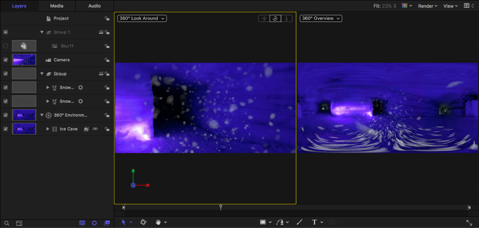
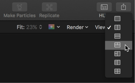
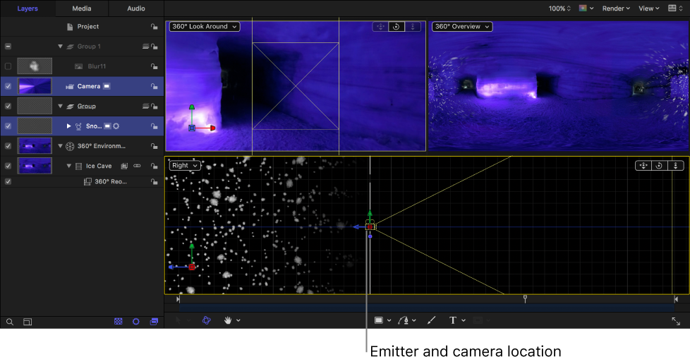
In the canvas, click the gray box in the top-right corner, then choose the fourth arrangement in the list (two viewports above, large viewport below).
The Top view of the 3D scene is displayed in the lower viewport. If necessary, drag the Dolly and Pan controls in the canvas to adjust the view so that the camera and particle emitter are both visible.
In the Layers list, select the camera, then drag the Position parameters from the Properties Inspector to the emitter in the Layers list.
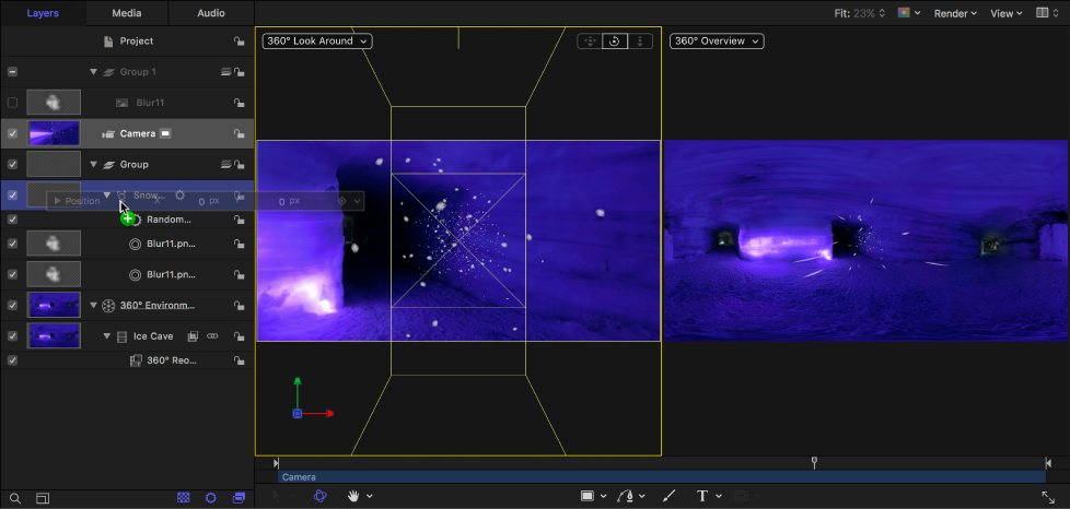
The emitter is moved to the same position as the camera.
In the canvas, click the Camera pop-up menu, then choose a side view (Left or Right).
In the Layers list, select the Emitter, then do one of the following:
In the canvas, drag the green arrow up to move the emitter vertically along the Y axis.
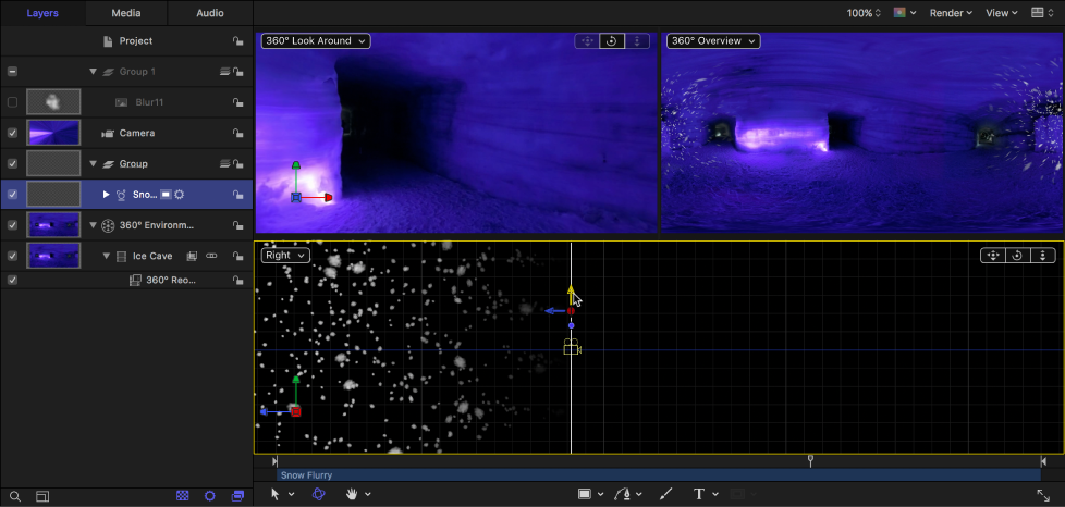
In the Properties Inspector, increase the Y Position parameter.
In the Emitter Inspector, choose Box from the Shape pop-up menu and ensure that the 3D checkbox is selected.
So that the particles fall downward, set the emitter’s Emission Angle to approximately 270°.
Note: You can also use the Gravity behavior (in the Simulations category) to control how the particles fall over time.
If necessary, adjust the Life, Birth Rate, Size, or other parameters in the Emitter Inspector—so the particles are more visible.
Because the emitter is directly above the camera (and its particles surround the camera), snow appears to fall all around the viewer.