Advanced Replicator Controls
The Replicator Inspector gives you control over every aspect of a replicator pattern. This includes parameters for the replicator cell (for replicators with a single cell).
Select a replicator.
In the Inspector, click Replicator.
The replicator parameters appear.
The contents of the Replicator Inspector are dynamic: different parameters appear depending on the option you choose in the Shape pop-up menu. Also, different parameters appear depending on the option you choose in the Arrangement pop-up menu.
The Difference Between Replicator and Replicator Cell Parameters
Replicator and replicator cell parameters, though closely related, serve different purposes. Replicator parameters control the overall shape, arrangement, offset, stacking order, build order, and number of elements in the replicator pattern.
Replicator cell parameters control the behavior and appearance of the elements in the replicator pattern. For more information, see Displaying Replicator Cell Parameters.
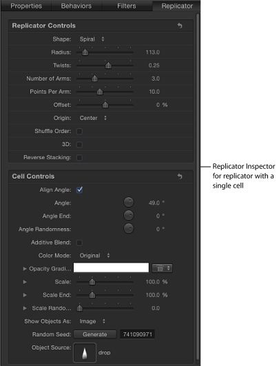
For a replicator with only one cell (one source layer), the replicator and replicator cell controls appear in the same Replicator Inspector. In this case, you can control every aspect of the replicator using these controls.
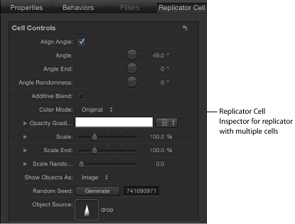
In replicators with multiple cells, each cell has its own Replicator Cell Inspector containing all parameters for that cell.
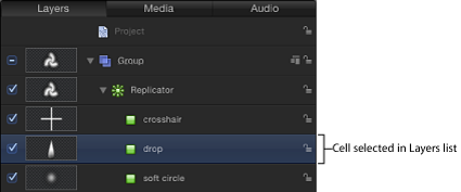
To access cell-specific parameters, select a cell in the Layers list or Timeline.
Replicator Controls in the Inspector
The controls in the Replicator Inspector give you complete control over every aspect of the pattern created by the selected replicator. This includes the shape upon which the pattern is built and the shape’s related parameters, such as the size of the pattern, how the elements are arranged in the pattern, and so on.
- Shape: The Shape pop-up menu sets the overall shape of the onscreen replicator pattern. The default setting is Rectangle. Choose any of up to ten shape styles from the menu to alter the distribution of the pattern elements.
Note: Depending on the item you choose in the Shape pop-up menu, additional controls may appear in the Replicator Inspector. For example, when Rectangle is selected in the Shape pop-up menu, the Outline, Tile Fill, and Random Fill options become available in the Arrangement pop-up menu. These additional controls let you further customize the chosen shape.
The Shape pop-up menu contains the following items:
- Line: Elements are positioned on a line. In the Inspector, you can set a specific number of points on the line—one element is positioned at every point (including the end points of the line). The Line shape displays additional Start Point, End Point, Points, and Offset parameters.
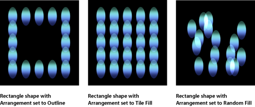
- Rectangle: Elements are positioned in a rectangle along the replicator outline, or in a tile or random fill pattern. When Rectangle is selected, the Arrangement parameter becomes available. Depending on the selected Arrangement, the Rectangle shape displays additional parameters.
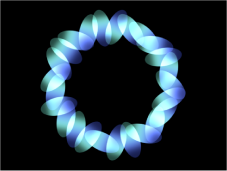
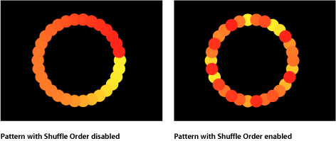
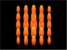
- Circle: Elements are positioned in a circle along the replicator outline, or in a tile or random fill pattern. When Circle is selected, the Arrangement parameter becomes available. Depending on the selected Arrangement, the Circle shape displays additional parameters. In the following image, the circle’s Arrangement is set to Outline.
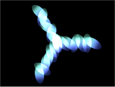
- Burst: Elements are positioned in a flare pattern. The Burst shape displays additional Radius, Number of Arms, Points Per Arm, Offset, and Origin parameters in the Replicator Inspector.
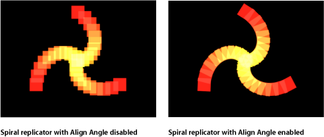
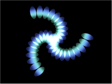
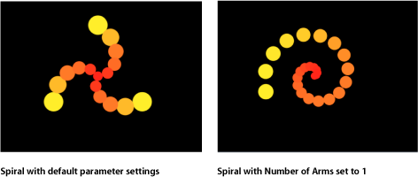
- Spiral: Elements are positioned in a spiral pattern. The Spiral shape displays additional Radius, Twists, Number of Arms, Points Per Arm, and Offset parameters in the Replicator Inspector.
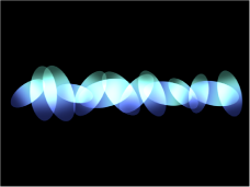
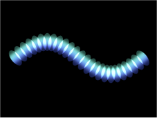
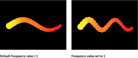
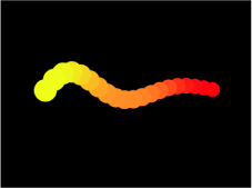
- Wave: Elements are positioned on a waveform. The Wave shape displays additional Start and End Point, Amplitude, Frequency, Phase, Damping, Points, and Offset parameters in the Replicator Inspector.
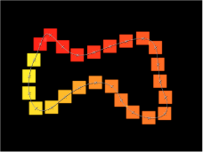
- Geometry: Elements are positioned along the edge of a shape, defined by a spline object used as the shape source. The Geometry shape displays additional Shape Source, Points, and Offset parameters in the Replicator Inspector.
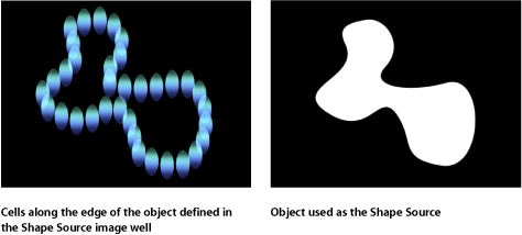
For information on using geometry (a shape) as a replicator shape, see Replicator Cell Controls in the Inspector.
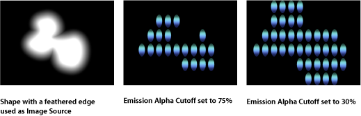
- Image: Elements appear within an area defined by an image or along its border, depending on what is chosen from the Arrangement pop-up menu. The image may have an alpha channel. If so, the shape of the alpha channel can also be used to define the pattern. When Image is selected, the Arrangement parameter becomes available. Depending on the selected Arrangement, the Image shape displays additional parameters.
For information on using an image as a replicator shape, see Using Image and Geometry Objects.
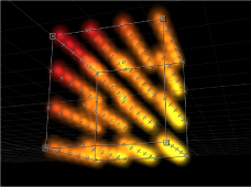
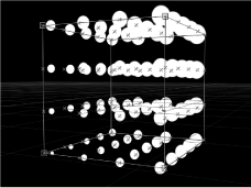
- Box: This option is available when the 3D checkbox is selected in the Replicator Inspector. Elements are positioned in a three-dimensional cube along the replicator outline, or on its surface in a tile or random fill pattern. Using the onscreen controls (with the Adjust Item tool), you can specify the size and location of the rectangle. Drag the front horizontal edge to adjust height; drag the front vertical edge to adjust width; drag a back edge to adjust depth; drag a front corner to simultaneously adjust the width and height. To reposition the replicator, drag in the replicator (but not on an edge or corner point). Depending on the selected Arrangement, the Box shape displays additional parameters. In the following image, the box’s Arrangement is set to Tile.
- Sphere: This option is available when the 3D checkbox is selected in the Replicator Inspector. Elements are positioned in a three-dimensional sphere along the replicator outline, or on its surface in a tile or random fill pattern. Using the onscreen controls (with the Adjust Item tool), you can specify the radius and location of the circle. Drag the outline of the sphere to adjust its radius; drag in the sphere to reposition it in the Canvas. When Sphere is selected, the Arrangement parameter becomes available. Depending on the selected Arrangement, the Sphere shape displays additional parameters.
- Arrangement: This pop-up menu, available when Shape is set to Rectangle, Circle, Image, Box, or Sphere, specifies the layout of the elements in the selected shape. The arrangement options are:
- Outline: Elements are positioned along the edge of the shape.
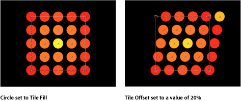
- Tile Fill: Elements are positioned in a tiled pattern of rows and columns in the circle, rectangle, image, box, or sphere pattern. You can specify the number of columns and rows, as well as the Tile Offset.
- Random Fill: Elements are positioned randomly from within circle, sphere, rectangle, or box.
- Size: This slider is available when Shape is set to Rectangle or Box. Click the disclosure triangle to display separate Width, Height, and Depth (for the Box shape) parameters. When Circle is the selected shape, this parameter becomes Radius.
Note: For projects using the default camera settings and a default Z position for the replicator, the Height is measured in pixels; however, the Width is measured in square pixels. This is done so a shape that is numerically square appears square when “Correct for Aspect Ratio” is selected in the View pop-up menu in the top-right corner of the Canvas.
- Emission Alpha Cutoff: When the Image Source object contains an alpha channel, this slider defines the minimum opacity value necessary to create an element at that point on the source image. For example, when set to 25%, elements only appear at points where the alpha value of the image is equal to or greater than 25% opacity. The lower the Emission Alpha Cutoff value, the more cells appear. For this parameter to be effective, the alpha channel must have areas of varying transparency.
- Start Point: This parameter is available when Shape is set to Line or Wave. Two value sliders define, in X, Y, and Z coordinates, the first point of the line or wave on which the elements are positioned. Click the disclosure triangle to access the Z Start Point value slider. You can adjust these values in the Canvas using the onscreen controls (with the Adjust Item tool).
- End Point: This parameter is available when Shape is set to Line or Wave. Two value sliders define, in X, Y, and Z coordinates, the second point of the line or wave on which the elements are positioned. Click the disclosure triangle to access the Z Start Point value slider. You can adjust these values in the Canvas using the onscreen controls (with the Adjust Item tool).
- Phase: This slider, available only when Shape is set to Wave. A dial defines the degree of offset of the waves from the start and end points of the path. When set to 0 degrees (default), the wave begins and ends at half the distance from the highest point to the lowest point in the wave. When set to 90 degrees, the wave begins and ends at the highest point in the wave. When set to –90 degrees, the wave begins at the lowest point in the wave. When set to 180 degrees, the waves are the same as 0 degrees, but inverted.
- Points: When Shape is set to Rectangle, Circle, Image, Box, or Sphere, and Arrangement is set to Outline or Random Fill, this slider specifies the number of evenly distributed element points along the edge of the shape.
When Shape is set to Line or Wave, the slider sets the number of evenly distributed element points on the line or wave. When the Adjust Item tool is selected, the points are visible in the Canvas.
When Shape is set to Geometry, the slider sets the number of evenly distributed element points around the shape.
- Offset: When Shape is set to Line or Wave, adjusting this slider moves the elements along the line or wave.
When Shape is set to Rectangle, Circle, Image, Box, or Sphere, and Arrangement is set to Outline, adjusting this slider moves the elements along the edge of the shape.
When Shape is set to Geometry, adjusting this slider moves the position of the elements along the edge of the shape.
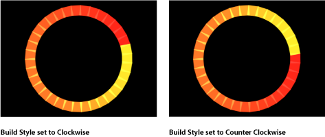
- Build Style: This pop-up menu and its options appear depending upon the selected Shape and Arrangement. Build Style specifies the how elements are built over the replicator shape.
For Rectangle, Circle, and Image replicator shapes with Arrangement set to Outline, or for a Geometry shape, the Build Style options are:
- Clockwise: Places the elements along the shape in a clockwise direction.
- Counter Clockwise: Places the elements along the shape in a counterclockwise direction.
For Rectangle and Image shapes with Arrangement set to Tile Fill and Origin set to Upper Left, Upper Right, Lower Left, or Lower Right, the Build Style options are:
- Across: Builds the elements across the pattern in the direction implied by the Origin parameter.
- By Row: Builds the elements over the pattern by row.
- By Column: Builds the elements over the pattern by column.
For Box shapes with the Arrangement set to Tile Fill and Origin set to Front Upper Left, Front Upper Right, Front Lower Left, Front Lower Right, Back Upper Left, Back Upper Right, Back Lower Left, or Back Lower Right, the Build Style options are:
- Across: Builds the elements across the pattern in the direction implied by the Origin parameter.
- By Row, Column, Rank: Builds the elements over the pattern by row, column, then rank starting from the Origin.
- By Column, Row, Rank: Builds the elements over the pattern by column, row, then rank starting from the Origin.
- By Row, Rank, Column: Builds the elements over the pattern by row, rank, then column starting from the Origin.
- By Column, Rank, Row: Builds the elements over the pattern by column, rank, then row starting from the Origin.
- By Rank, Row, Column: Builds the elements over the pattern by rank, row, then column starting from the Origin.
- By Rank, Column, Row: Builds the elements over the pattern by rank, column, then row starting from the Origin.
- Columns: This slider, available when Shape is set to Rectangle, Circle, or Image (with Arrangement set to Tile Fill), or when Shape is set to Box or Sphere (with Arrangement set to Outline or Tile Fill), specifies the number of vertical columns (or horizontal element points) on a grid over the selected replicator. In the case of an irregular shape (nonrectangular), points that fall outside the shape are ignored.
- Rows: This slider, available when the Arrangement parameter is set to Tile Fill, specifies the number of horizontal rows (or vertical element points) on a grid over the selected replicator. In the case of an irregular shape (nonrectangular), points that fall outside the shape are ignored. This control is also available for Box and Sphere when Arrangement is set to Outline or Tile Fill.
- Ranks: This slider, available when Shape is set to Box (with Arrangement set to Tile Fill or Outline), or Sphere (with Arrangement set to Tile Fill), specifies the number of points in Z space on a grid over the selected replicator. In the case of an irregular shape (nonrectangular), points that fall outside the shape are ignored.
- Tile Offset: This slider, available when Shape is set to Rectangle, Circle, Image, Box, or Sphere, and Arrangement is set to Tile Fill, specifies the amount (in percentage points) that the elements are offset from the pattern. Values from 0 to 100% offset the rows toward the right, and values from 0 to –100% offset the rows toward the left. A value of 50 or –50% creates a brickwork pattern.
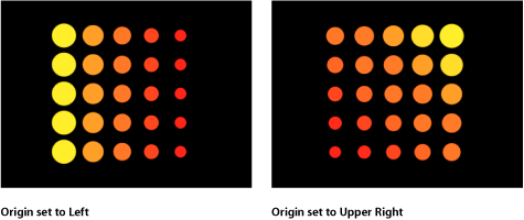
- Origin: This pop-up menu, available when Shape is set to Rectangle, Circle, Image, Box, or Sphere, and Arrangement is set to Tile Fill or Random Fill, specifies how the elements traverse across the pattern from a point of origin. For example, when set to Left, the elements sweep across the pattern from left to right. When set to Upper Right, the elements traverse from the upper-right corner point of the shape to the lower-right corner.
The Origin pop-up menu contains the following items:
- Upper Left: The elements originate in the upper-left corner of the pattern and end in the lower-right corner.
- Upper Right: The elements originate in the upper-right corner of the pattern and end in the lower-left corner.
- Lower Left: The elements originate in the lower-left corner of the pattern and end in the upper-right corner.
- Lower Right: The elements originate in the lower-right corner of the pattern and end in the upper-left corner.
- Center: The elements originate in the center of the pattern and move outward. This is the default Origin option.
- Left: The elements originate at the left side of the pattern and end at the right side.
- Right: The elements originate at the right side of the pattern and end at the left side.
- Top: The elements originate at the top of the pattern and end at the bottom.
- Bottom: The elements originate at the bottom of the pattern and end at the top.
When Circle or Sphere is chosen from the Shape pop-up menu and Arrangement is set to Tile Fill or Random Fill, the Origin options are:
- Center: The elements originate in the center of the pattern and build outward. This is the default Origin option.
- Edge: The elements originate along the edge of the pattern and build inward.
When Box is chosen from the Shape pop-up menu and Arrangement is set to Tile Fill or Random Fill, the Origin options are:
- Front Upper Left: The elements originate in the front upper-left corner of the pattern and end in the back lower right.
- Front Upper Right: The elements originate in the front upper-right corner of the pattern and end in the back lower left.
- Front Lower Left: The elements originate in the front lower-left corner of the pattern and end in the back upper right.
- Front Lower Right: The elements originate in the front lower-right corner of the pattern and end in the back upper left.
- Back Upper Left: The elements originate in the back upper-left corner of the pattern and end in the front lower right.
- Back Upper Right: The elements originate in the back upper-right corner of the pattern and end in the front lower left.
- Back Lower Left: The elements originate in the back lower-left corner of the pattern and end in the front upper-right.
- Back Lower Right: The elements originate in the back lower-right corner of the pattern and end in the front upper-left.
- Left: The elements originate at the left side of the pattern and end at the right side. The pattern is identical on each row.
- Right: The elements originate at the right side of the pattern and end at the left side. The pattern is identical on each row.
- Top: The elements originate at the top of the pattern and end at the bottom. The pattern is identical on each rank.
- Bottom: The elements originate at the bottom of the pattern and end at the top. The pattern is identical on each rank.
- Front: The elements originate at the front of the pattern and end at the back. The pattern is identical on each column.
- Back: The elements originate at the back of the pattern and end at the front. The pattern is identical on each column.
- Center: The elements originate in the center of the pattern and move outward. This is the default Origin option.
- X Axis: The elements originate along the X axis of the pattern and move outward.
- Y Axis: The elements originate along the Y axis of the pattern and move outward.
- Z Axis: The elements originate along the Z axis of the pattern and move outward.
Note: The origin parameter also determines where the Sequence Replicator behavior starts its animation. For more information on the Sequence Replicator behavior, see Using the Sequence Replicator Behavior.
- Replicate Seed: This parameter, available when Shape is set to Rectangle, Circle, Image, Box, or Sphere, and Arrangement is set to Random Fill, modifies the Random Fill pattern. Click the Generate button to set a new random seed number.
Although the result of the Random Fill option from the Arrangement pop-up menu seems random, it’s deterministic. This means that the random variation in the pattern is created based on the number shown. Unless this seed number is changed, a replicator with the same parameter settings and source object always appears the same. If you don’t like the current random fill, you can change the seed number by typing a new number or clicking Generate. This changes the random calculations performed for that pattern. This parameter is also used to randomize the Shuffle Order parameter.
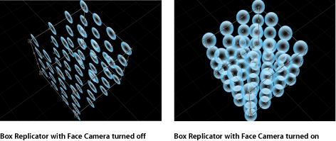
- Face Camera: When this checkbox is selected, the pattern elements actively face the camera when the camera or the replicator is rotated. When Face Camera is deselected, the elements face forward in the replicator pattern and appear flat (unless the source layer or pattern elements are rotated in 3D space). Because Motion only supports 2D objects, this option is key to giving 2D objects the appearance of 3D as the camera is animated.
Note: Because replicator pattern elements are 2D (flat) objects, the pattern elements are not visible when you use the orthogonal camera views, such as Left, Right, and Top (unless the source layer or pattern elements are rotated in 3D space). This is because orthogonal views are at right angles (perpendicular) to the elements. For more information on using cameras, see Cameras.
Displaying Replicator Cell Parameters
The replicator cell parameters modify the individual elements in the onscreen pattern. In a replicator with only a single cell, the cell parameters appear in two locations: the lower portion of the Replicator Inspector and the Replicator Cell Inspector. In a replicator with multiple cells, each cell has its own Replicator Cell Inspector that contains all parameters for that cell.
In the Layers list, Timeline, or Canvas, select a replicator layer.
In the Inspector, open the Replicator pane.
The cell parameters appear in the Cell Controls group.
In the Layers list or Timeline, select a cell (located beneath the replicator layer).
In the Inspector, open the Replicator Cell pane.
In the Layers list or Timeline, select a cell (located beneath the replicator layer).
In the Inspector, open the Replicator Cell pane.
Replicator Cell Controls in the Inspector
These controls appear at the bottom of the Replicator Inspector (for replicators with a single cell) or in the Replicator Cell Inspector (for replicators with multiple cells).
- Angle: A dial that specifies (in degrees) the rotation of the replicator elements. When the 3D checkbox is selected in the Replicator Inspector, the default dial modifies the Z angle. To modify the rotation of the pattern elements on all three axes (X, Y, and Z), click the disclosure triangle and adjust the X, Y, and Z dials.
When the 3D checkbox is selected, this parameter also displays the Animate pop-up menu.
- Animate: A pop-up menu that sets the angle interpolation for keyframed animation of the Angle parameter. There are two choices:
Use Rotation: The default interpolation method. When the Angle parameter is keyframed, pattern elements rotate from their start rotation to their final rotation. Depending on the animation, the elements may twist before reaching their final orientation (the last keyframed value). For example, if the X, Y, and Z Angle parameters are animated from 0 degrees to 180 degrees in a project, the elements rotate on all axes before reaching their final orientation.
Use Orientation: This alternate interpolation method provides smoother animation but does not allow multiple revolutions. It interpolates between the pattern elements’ start orientation (first keyframe) and their end orientation (second keyframe).
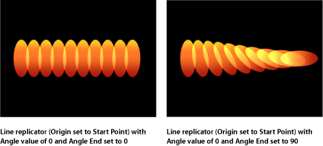
- Angle End: A dial that specifies (in degrees) the rotation of the replicator elements at the end of the pattern. The angle value of the elements at the end of the pattern equals the Angle value (start) plus the Angle End value. For example, if Angle is set to 0 degrees and Angle End set to 90 degrees, the elements are not rotated at all at their origin, and are rotated by 90 degrees at the end of the pattern.
In a 3D project, using the default dial modifies the Z angle. To modify the rotation of the pattern elements on all three axes (X, Y, and Z), click the disclosure triangle and adjust the individual X, Y, and Z dials.
When the 3D checkbox is selected, Angle End also displays the Animate pop-up menu.
- Animate: A pop-up menu that sets the angle interpolation for keyframed animation of the Angle parameter. There are two choices:
Use Rotation: This is the default interpolation method. When the Angle End parameter is keyframed, pattern elements rotate from their start rotation to their final rotation. Depending on the animation, the elements may twist before reaching their final orientation (the last keyframed value). For example, if the X, Y, and Z Angle parameters are animated from 0 degrees to 180 degrees in a project, the elements rotate on all axes before reaching their final orientation.
Use Orientation: This alternate interpolation method provides smoother animation but does not allow multiple revolutions. It interpolates between the pattern elements’ start orientation (first keyframe) and their end orientation (second keyframe).
- Angle Randomness: A dial that defines an amount of variance in the rotation of replicator elements. A value of 0 results in no variance—all elements have the same rotational value. A value greater than 0 introduces a variance. The angle for an element is defined by the Angle and Angle End parameter, plus or minus a random value falling within the Angle Randomness.
In a 3D project, using the default dial or value slider (when the disclosure triangle is closed), modifies the Z angle. To modify the rotation of the pattern elements on all three axes (X, Y, and Z), click the disclosure triangle and adjust the X, Y, and Z dials.
When the 3D checkbox is selected, this parameter also displays the Animate pop-up menu.
- Animate: A pop-up menu that sets the angle interpolation for keyframed animation of the Angle Randomness parameter. There are two choices:
Use Rotation: This is the default interpolation method. When the Angle Randomness parameter is keyframed, pattern elements rotate from their start rotation to their final rotation. Depending on the animation, the elements may twist before reaching their final orientation (the last keyframed value). For example, if the X, Y, and Z Angle parameters are animated from 0 degrees to 180 degrees in a project, the elements rotate on all axes before reaching their final orientation.
Use Orientation: This alternate interpolation method provides smoother animation but does not allow multiple revolutions. It interpolates between the pattern elements’ start orientation (first keyframe) and their end orientation (second keyframe).
- Additive Blend: By default, replicator elements are composited together using the Normal blend mode. Select this checkbox to composite all overlapping elements using the Additive blend mode. This blending occurs in addition to the compositing method set in the Properties Inspector. The result is that the brightness of overlapping objects is intensified.
- Color Mode: This pop-up menu specifies the origin of the color for replicated elements There are five menu options:
- Original: Elements are created using the original colors from the source layer. When Original is chosen, the Opacity Gradient editor appears, allowing you to change the opacity of the replicator elements over the pattern.
- Colorize: Elements are tinted using the color specified in the Color parameter. Additional Color and Opacity Gradient parameters appear.
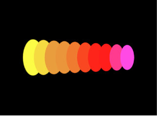
- Over Pattern: Elements are tinted based on how they are ordered in the pattern. When Over Pattern is chosen, the Color Gradient editor appears, allowing you to define the range of color of the pattern, beginning with the leftmost color in the gradient, and progressing through the range of colors until reaching the rightmost color at the end of the pattern.
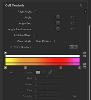
Gradual color changes do not appear in each element, but only across the pattern as a whole. An Opacity control is available at the top of the gradient editor.
- Pick From Color Range: Elements are tinted at random, with the range of possible colors defined by the Color Range gradient editor, which appears when you choose Pick From Color Range. A point on the gradient is randomly chosen, so the relative sizes of each color region determine the frequency of the color being used.
For more information on using the gradient controls, see Using the Gradient Editor.
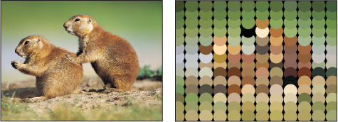
- Take Image Color: Each element’s color is based on the color of the image at the position of the element point. This mode is only available when an image in used as the replicator shape.
- Color: This color well becomes available when the Color Mode is set to Colorize. Use it to specify a color to tint replicator elements. You can also alter each element’s opacity. This parameter is unique to the cell object. You can click the color well to choose a color, or open the disclosure triangle and use the Red, Green, Blue, and Opacity channel sliders or value sliders.
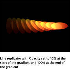
- Opacity Gradient: This gradient editor appears when Color Mode is set to Original or Colorize. Use it to change the opacity of the replicator elements over the pattern. This gradient control is limited to grayscale values, which are used to represent varying levels of transparency. White represents solid elements; progressively darker levels of gray represent decreasing opacity; and black represents complete transparency. A simple white to black gradient represents a pattern that is solid at its origin, but which fades out gradually. For more information on using gradient and opacity gradient controls, see Using the Gradient Editor.
- Color Repetitions: When Color Mode is set to Over Pattern, this parameter becomes available. Drag the slider to increase the number of times the gradient is repeated over the pattern. For more information on using gradient controls, see Using the Gradient Editor.
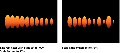
- Scale: This slider defines the scale of replicator elements. Click the disclosure triangle next to the Scale parameter to reveal separate X Scaling and Y Scaling subparameters that can be used to adjust the width and height of elements separately. By default, Scale is set to 100%—the size of the replicator elements is equal to the size of the source layer.
- Scale Randomness: This slider defines an amount of variance in the scale of replicator elements. A value of 0 results in no variance—all elements in the pattern are the same size. A value greater than 0 introduces a variance. The scale for an element is defined by the Scale parameter, plus or minus a random value falling within the Scale and the Scale End. The disclosure triangle of the Scale Randomness parameter reveals separate X and Y subparameters that can be used to set width and height values separately.
- Play Frames: This checkbox appears if the replicator is using a QuickTime object as the source for a cell. When this checkbox is selected, playback of the animation or movie clip used for each element will loop. If this checkbox is deselected, the animation or clip is frozen at the still frame specified by the Random Start Frame parameter or the Source Start Frame parameter.
- Random Start Frame: This checkbox appears if the replicator is using a QuickTime object as the source for a cell. Use this control to introduce variation into elements using QuickTime animation or movies as their source objects. When this checkbox is selected, each element in the pattern begins at a different frame of the clip. Stills are chosen randomly if Play Frames is deselected.
- Source Start Frame: This slider appears if the replicator is using a QuickTime object as the source for a cell. The value selected in the slider designates the start frame of the clip (when the Play Frames checkbox is selected) or the still frame to display (when Play Frames is deselected). This parameter appears only if Random Start Frame is deselected.
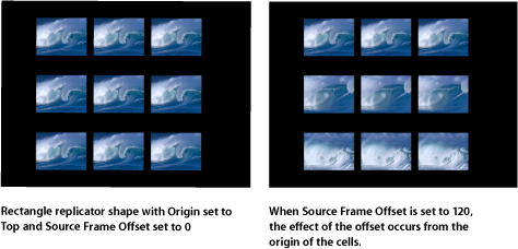
- Source Start Frame Offset: This slider, which appears if the replicator is using a QuickTime object as the source for a cell, and if Random Start Frame is deselected, offsets the start frame chosen in the Source Start Frame parameter over the pattern. At their origin, the elements play the animation from the frame specified in the Source Start Frame parameter. Each step away from the origin advances the start frame by the offset amount.
- Show Objects As: Use this pop-up menu to set the display of replicator elements to a preview mode, or as they actually appear. The nonimage modes play back more efficiently when viewing a complex replicator pattern. By default, this pop-up menu is set to Image, which displays each element as it is supposed to appear. Choose one of the following four options:
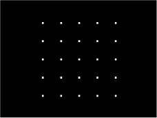
- Points: Each element is represented by a single point. This is the fastest preview mode. When you choose Points, the Point Size slider appears, allowing you to increase the size of the points for easier viewing. In the following image, the Point Size is set to 8.
- Lines: This option is effective only when the elements of the replicator are animated using Simulation behaviors or the Throw (Basic Motion) behavior. The movement of each pattern element is represented by a line and is useful in analyzing the vector of each element’s motion. The length of each line is determined by that element’s speed, and the angle of each line equals each element’s direction. In the following image, the replicator elements are animated using the Vortex behavior.
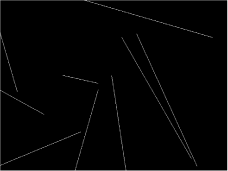
Note: Element movement created by the Sequence Replicator behavior or by keyframing the replicator parameters is not displayed.
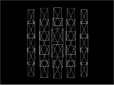
- Wireframe: Each pattern element is represented by a bounding box. Because the bounding boxes are good indicators of each element’s orientation in the pattern, this preview mode is useful for evaluating the movements of individual elements. For example, it’s easy to see the angle of rotation for elements that are spinning or following a complex motion path.
- Image: This option displays the elements as they are supposed to appear in your final render.
Note: Whatever is selected in the Show Objects As pop-up menu appears in your final render.
- Random Seed: Although the result of adjusting the Angle Randomness, Scale Randomness, Pick From Color Range, Random Start Frame, or Hold Frame Randomness parameters seems random, it’s deterministic. This means that the random variation in the pattern is created based on the number shown in the Random Seed field. Unless this seed number is changed, a replicator with the same parameter settings appears the same. If you don’t like the current random scale or angle, change the seed number by typing a new number the field or by clicking Generate.
- Object Source: This image well displays a thumbnail of the replicator. To swap out a cell, drag a replacement cell from the Layers list to the Object Source well.
In a replicator with multiple cells, each cell appears in a separate image well listed at the bottom of the Replicator Inspector. A checkbox allows you to enable or disable that cell.