How Subtractive Synthesizers Work
There are a number of approaches to sound creation with a synthesizer (see Other Synthesis Methods). Although there are numerous differences between synthesizer models, most follow a fundamentally similar architecture and signal flow that is based on subtractive synthesis principles.
According to legend, when Michelangelo was asked how he managed to carve David out of a block of stone, he replied, “I just cut away everything that doesn’t look like David.”
In essence, this is how subtractive synthesis works:You filter (cut away) the parts of the sound that you don’t want to hear. In other words, you subtract parts of the frequency spectrum, consisting of the fundamental tone and associated harmonics.
The subtractive approach to synthesis assumes that an acoustic instrument can be approximated with a simple oscillator—which produces waveforms with different frequency spectrums. The signal is sent from the oscillator to a filter that represents the frequency-dependent losses and resonances in the body of the instrument. The filtered (or unfiltered) signal is shaped over time by the amplifier section of the synthesizer.
The distinctive timbre, intonation, and volume characteristics of a real instrument can theoretically be recreated by combining these components in a way that resembles the natural behavior of the instrument you are trying to emulate.
In reality, however, because subtractive synthesizers aren’t ideal for emulating real world instruments, no synthesized clarinet is going to fool anyone—particularly now that there are multigigabyte sound libraries available for samplers like the EXS24 mkII.
The real strength of subtractive synthesizers is that they offer a unique sound palette of their own.
All analog and virtual analog synthesizers use subtractive synthesis to generate sound.
An Overview of Subtractive Synthesizer Components
The front panel of most subtractive synthesizers contains a collection of similar signal generating and processing modules—coupled with a number of modulation and control modules. The signal-generating and processing modules typically run left to right, mirroring the actual synthesizer signal flow.
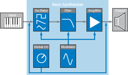
- Oscillators: Generate the basic signal. This is usually a waveform that is rich in harmonics (see Oscillators). Many synthesizers offer more than one oscillator.
- Filter section: Used to alter the basic signal by filtering out (removing) portions of the frequency spectrum. Many synthesizers offer a single filter, which is applied universally to all oscillator signals. Multioscillator synthesizers can provide multiple filters, allowing each oscillator signal to be filtered in a different way (see Filters).
- Amplifier section: Used to control the level of the signal over time. The amplifier features a module known as an envelope, which is broken down into several elements that provide level control for the beginning, middle, and end portions of your sound. Simple synthesizers generally offer a single envelope, which is used to control the oscillator (and filter) over time. More complex synthesizers can feature multiple envelopes (see Envelopes in the Amplifier Section).
- Modulators: Used to modulate the signal-generating and processing components. Modulations can be machine-based—automatically generated by a synthesizer component—or can be manually activated by using the modulation wheel, for example. Most synthesizers provide a component called an LFO (low frequency oscillator) to provide a waveform that modulates the signal. See Modulation.
- Global controls: Affect the overall characteristics of your synthesizer sound, such as glides between notes, pitch bend, monophonic or polyphonic playback, and more (see Global Controls).
Oscillators
The audio signal of a synthesizer is generated by the oscillator. Usually you would choose from a selection of waveforms that contain differing types and varying amounts (more or fewer) of harmonics. The level relationships between the fundamental tone and the harmonics of the chosen waveform are responsible for the basic sound color or timbre.
Common Synthesizer Waveforms
The qualities of the most common synthesizer waveforms are discussed below.
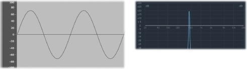
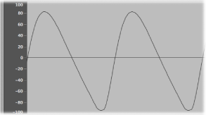
Clean and clear-sounding, a sine wave contains no harmonics but the first harmonic; in other words, it is the fundamental tone. The sine wave—used standalone—can be used to create “pure” sounds like whistles, the sound of wet fingers on the rim of a glass, tuning forks, and so on.
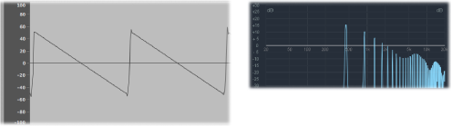
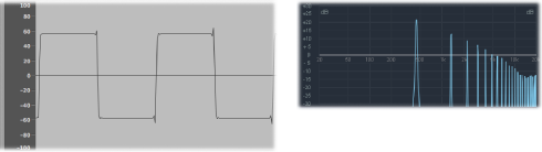
Clear and bright-sounding, a sawtooth wave contains both odd and even harmonics. It is ideal for the creation of string, pad, bass, and brass sounds.
Hollow and woody-sounding, a square wave can contain a wide range of odd harmonics. It is useful when creating reed instruments, pads, and basses. It can also be used to emulate kick drums, congas, tom-toms, and other percussive instruments—often blended with another oscillator waveform, such as noise.
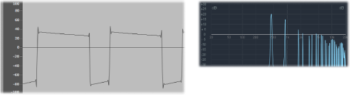
The square wave can be reshaped to make the waveform cycles—or pulses—more rectangular on many synthesizers, using a pulse width modulation (PWM) control. The more rectangular the wave becomes, the more nasal it sounds. When modulated in this way, the square wave is known as a pulse wave, and contains fewer harmonics. It can be used for reeds, basses, and brass sounds. See Reshaping Waveforms.
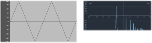
Like a square wave, a triangle wave contains only odd harmonics. Because a triangle wave’s higher harmonics roll off faster than the ones of a square wave, the triangle wave sounds softer. It is ideal for creating flute sounds, pads, and vocal “oohs.”
Noise is useful for emulating percussive sounds, such as snare drums, or wind and surf sounds, among others.
- White noise: The most common noise waveform found on synthesizers. White noise contains all frequencies—at full level—around a center frequency.
- Pink and red noise: These noise colors also contain all frequencies, but they are not at full level across the frequency spectrum. Pink noise decreases the level by 3 dB per octave (of higher frequencies). Red noise decreases the level by 6 dB per octave.
- Blue noise: Blue noise, which is the reverse of pink noise, increases the level of all frequencies in higher octaves by 3 dB.
There are other noise wave colors, but they aren’t commonly found in synthesizers.
Reshaping Waveforms
It is possible to deform the basic waveforms to create new waveforms. This results in a different timbre, or tonal color, thus expanding the palette of sounds that can be created.
There are many ways to reshape a waveform. The most obvious would be altering the pulse width of a square wave, as discussed in Common Synthesizer Waveforms. Other waveform-altering options include changing the phase angle, moving the start point of a waveform cycle, or simply combining multiple waveforms in multioscillator synthesizers.
When reshaped in these and other ways, the relationships between the fundamental tone and other harmonics change, thus altering the frequency spectrum and the basic sound being produced.
Filters
The purpose of the filter in a subtractive synthesizer is to remove portions of the signal—the frequency spectrum—that is sent from the oscillators. After being filtered, a brilliant-sounding sawtooth wave can become a smooth, warm sound without sharp treble.
The filter sections of most subtractive synthesizers contain two primary controls known as cutoff frequency—often simply called cutoff—and resonance. Other filter parameters can include drive and slope. The filter section of most synthesizers can be modulated by envelopes, LFOs, the keyboard, or other controls such as the modulation wheel.
Types of Filters
There are several filter types. Each has a different effect on various portions of the frequency spectrum:
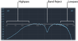
- Lowpass filter: Low frequencies are passed; high frequencies are attenuated.
- Highpass filter: High frequencies are passed; low frequencies are attenuated.
- Bandpass filter: Only frequencies within a frequency band are passed.
- Band Reject filter: Only frequencies within a frequency band are attenuated.
- Allpass filter: All frequencies in the spectrum are passed, but the phase of the output is modified.
Cutoff Frequency
The cutoff frequency, or cutoff, as the name suggests, determines where the signal is cut off. Simpler synthesizers offer only lowpass filters. Thus, if a signal contains frequencies that range from 20 to 4000 Hz, and a cutoff frequency is set at 2500 Hz, frequencies above 2500 Hz are filtered. The lowpass filter allows frequencies below the cutoff point of 2500 Hz to pass through, unaffected.
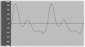
The figure below shows an overview of a sawtooth wave (A = 220 Hz). The filter is open, with cutoff set to its maximum value. In other words, this waveform is not being filtered.
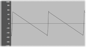
The figure below shows a sawtooth wave with the filter cutoff set to about a 50% value. This filter setting results in suppression of the higher frequencies and a rounding of the edges of the sawtooth wave, making it resemble a sine wave. Sonically, this setting makes the sound much softer and less brassy.
As you can see from this example, use of the filters to cut away portions of the frequency spectrum alters the waveform’s shape, thus changing the timbre of the sound.
Resonance
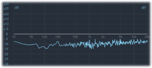
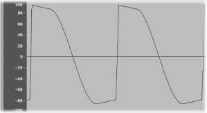
The resonance control emphasizes or suppresses signals around the cutoff frequency. The figure below shows an ES1 sawtooth wave with a high resonance setting and the cutoff frequency set to 660 Hz, which is about 60%.
This resonant filter setting results in much brighter and harsher signals close to the cutoff frequency. Frequencies below the cutoff point are unaffected.
Once again, the overall result of using filter resonance is a change in the basic waveform’s shape and, therefore, its timbre.
Very high filter resonance settings can be used to such an extreme degree that the filter begins to self-oscillate, resulting in the filter generating a sine wave.
Drive
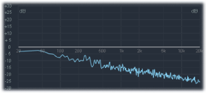
Drive adds an amount of gain to the waveform as it enters the filter—an input gain control—thus overdriving the filter and distorting the waveform. This waveform distortion changes the timbre of the sound, making it much harsher. See Reshaping Waveforms for more information about waveform distortions.
The figure shows an unfiltered sawtooth wave, with Drive set to about 80%. Notice that the wave cycles touch the floor and ceiling of the filter’s dynamic range.
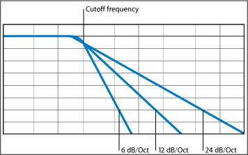
Filter Slope
As discussed earlier, a filter will cut off the signal at the set cutoff frequency. This cutoff doesn’t happen abruptly but rather at a given slope, which is measured in decibels (dB) of gain reduction per octave. Put another way, you can define how steep the “cliff” is at the cutoff point by choosing a relatively severe or more gentle slope.
Envelopes in the Amplifier Section
The amplifier module of a synthesizer is responsible for controlling the level—or loudness—of the signal over time.
To put this into a musical context, consider the sound of a violin, which slowly ramps up to a peak—or maximum—level as the bow is smoothly dragged across a string, is sustained for a period until the bow is moved away from the string, and then cuts off abruptly. In comparison, hitting a snare drum with a drumstick results in a very fast peak level, with no sustain portion, and the sound immediately dies out (although there will be an amount of decay, the time it takes to fall from the peak level). As you can see, these two sounds have very different characteristics over time.
Synthesizers emulate these sonic characteristics by providing control over different parts—the beginning, middle, and end—of a sound’s level over time. This control is achieved with a component called an envelope generator.
The Attack, Decay, Sustain, and Release (ADSR) Envelope Controls
An oscillogram of a percussive tone is shown below in which the level rises immediately to the top of its range and then decays. If you drew a box around the upper half of the oscillogram, you could consider it the “envelope” of the sound—an image of the level as a function of time. It is the function of the envelope generator to set the shape of this envelope.
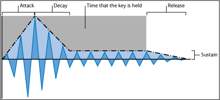
The envelope generator usually features four controls—attack, decay, sustain and release, commonly abbreviated as ADSR.
- Attack: Controls the time it takes for the initial slide from an amplitude of zero to 100% (full amplitude).
- Decay: Determines the time taken for the subsequent fall from 100% amplitude to the designated sustain level.
- Sustain: Sets the steady amplitude level produced when a key is held down.
- Release: Sets the time it takes for the sound to decay from the sustain level to an amplitude of zero when the key is released.
If a key is released during the attack or decay stage, the sustain phase is usually skipped. A sustain level of zero will produce a piano-like—or percussive—envelope, with no continuous steady level, even when a key is held.
Using the Envelope to Control Filters
Envelope generators are not limited to controlling signal amplitude. They can also control the rise and fall of the filter cutoff frequency or modulate other parameters. In other words, envelope generators can be used as a modulation source—or as a “remote control” for a given parameter, if you prefer.
This aspect of synthesizers—modulation—is covered in the following section.
Modulation
Without modulation, sounds tend to be boring and fatiguing to the ear. They also sound synthetic, rather than natural, in the absence of some type of sonic modulation. The most obvious type of modulation is vibrato, which is used by orchestral string players to add animation to an instrument’s pitch.
To make sounds more interesting, you can use various synthesizer controls to modulate basic sound parameters.
Modulation Routing
Many synthesizers, including the ES1, ES2, and EXS24 mkII sampler, feature a modulation router.
The router allows you to direct one or more modulation sources to one or more modulation targets—or destinations, if you prefer. For example, you can change modulation targets, such as the oscillator pitch or filter cutoff frequency, by using modulation sources that include the following:
- Velocity modulation: The impact of your keyboard playing (harder or softer).
- Key scaling: The position you play on the keyboard.
- Use of controls: These can include the modulation wheel, ribbon controllers, or pedals attached to your keyboard.
- Automatic modulation: You can use envelope generators or LFOs to modulate signals automatically.
Modulation Routing in the ES1 and ES2
The ES1 and ES2 provide an easy way to route a control—a modulation source—to part of the sound engine—a modulation target. For details on the use of the modulation facilities and other parameters, see the ES1 and Oscillator on/off buttons.
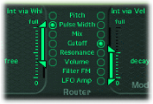
You can do modulation routing n the ES1 by selecting a modulation target in the left or right column of buttons in the Router section. You use the left column to set a modulation target that can be controlled, in amount, via the modulation wheel of your keyboard. The target you choose in the right column will dynamically respond to keyboard velocity. The amount, or range, of this modulation is determined by the two arrows shown in the sliders (Int via Whl and Int via Vel). The upper arrow determines the maximum amount of modulation, and the lower arrow determines the minimum amount of modulation.
The ES2 provides ten modulation routings—in columns. Although it looks somewhat intimidating at first, each routing column is quite similar to the modulation controls found in the ES1. Note the first routing, at the left in the figure below:
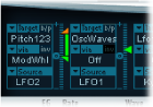
The modulation target is Pitch123. The pitch—the Frequency parameter—of oscillators one, two, and three is affected (by LFO2, the modulation source).
LFO2 is the modulation source. The two arrows to the right of the column indicate the modulation amount. To make the modulation more intense, drag the upper and/or lower arrows up or down, thereby increasing the range of the modulation amount. The upper arrow determines the maximum amount of modulation, and the lower arrow determines the minimum amount of modulation.
The Via control is the ModWhl. The amount of modulation—the range of which is determined by the sliders to the right of the channel—is directly controlled via the modulation wheel of your keyboard. When the modulation wheel is at the minimum setting, at the bottom of its travel, the amount of oscillator pitch modulation is minimal —or off/no modulation at all. As you move the modulation wheel upward, the frequency of all three oscillators is directly controlled by the LFO within the range determined by the sliders.
Common Modulation Sources
This section outlines modulation sources that you typically find on most synthesizers.
Modulation Controllers
Modulation sources can be—and often are—triggered by something you’ve done, such as played a note on the keyboard, or moved the modulation wheel.
Thus, the modulation wheel, pitch bend ribbons, foot pedals, keyboard, and other input options are referred to as modulation controllers, or simply controllers.
Perhaps the best example of a modulation controller in action would be the use of a velocity-sensitive keyboard, set up to control the filter and level envelopes. The harder you strike the notes, the louder and brighter the sound is. See Using Envelopes for Modulation.
Using the LFO to Modulate Sounds
A modulation source found on nearly all synthesizers is the LFO (low frequency oscillator). This oscillator is used only as a modulation source and does not generate any audible signals that form part of your actual synthesizer sound, because it’s too low to be heard. It can, however, affect the main signal by adding vibrato, filter sweeps, and so on.
The LFO generally offers the following controls:
- Waveform: Allows you to choose the type of waveform (triangle waves and square waves are seen most often). Triangle waves are useful for filter sweeps (slow changes to the filter cutoff frequency) or when simulating an ambulance siren (slow changes to the oscillator frequency). The square waveform is useful for rapid switches between two different pitches (vibratos or octaving, for example).
- Frequency/Rate: Determines the speed of the waveform cycles produced by the LFO. When set to low values, very slow ramps are produced, making it easy to create sounds such as ocean waves rolling in (when white noise is chosen as the waveform in the main oscillator).
- Sync mode: Allows you to choose between free running (a user-defined LFO rate) or synchronization with an external tempo source (such as a host application).
The LFO can also be controlled with an envelope generator in some synthesizers. As an example of where this might be useful, imagine a sustained string section sound where vibrato is introduced a second or so into the sustained portion of the sound. If this can happen automatically, it allows you to keep both hands on the keyboard.
In certain synthesizers, a simple envelope generator is included for this precise purpose. Often, this envelope consists only of an attack parameter, or occasionally it includes decay or release options. These parameters perform in the same fashion as the amplitude envelope parameters (see Envelopes in the Amplifier Section), but they are limited to control of LFO modulations.
Using Envelopes for Modulation
The main envelope generator of the synthesizer not only controls levels over time, but it also is often used to modulate other sound parameters when you press or release keyboard keys.
The most common use of envelope modulation is to control the filter cutoff and resonance parameters with the keyboard velocity or keyboard scaling modulation sources (see Modulation Routing).
Global Controls
This section covers global controls that affect the overall output signal of your synthesizer.
The most obvious global control is the Level control, which sets the overall loudness of your sound. For more information about the Level control, see Envelopes in the Amplifier Section.
Other key global controls include the following:
- Glide (sometimes called Portamento): Used to set the amount of time that it takes for one note pitch to slide up or down to another note pitch. This control is useful for emulating wind instruments that slide from note to note, rather than move directly to another clear and distinct pitch.
- Bender/Bend Range: This control is generally hard-wired to a Pitch Bend wheel on a keyboard. As the name suggests, moving the wheel up or down from its centered position bends the pitch (the oscillator frequency) up or down. The Bender/Bend Range parameter usually has an upper and lower limit of one octave but is typically set to around three semitones up or down. This setting is ideal for emulating small (or extreme) pitch fluctuations that occur in some instruments—such as when moving between notes with a trumpet, or bending the strings during a scorching guitar solo.
- Voices: Synthesizers have a limit to the number of notes that can be produced simultaneously. Producing notes simultaneously is known as the polyphony (literally, this means “many voices”) of the instrument. The Voices parameter sets an upper limit to the number of notes that can be played at a given time.
- Unison: Used to “stack” voices—with the unison voice being heard one octave above the frequency of the played note. Because two voices are being used when you play a note, unison has two effects—it makes the sound richer and fuller, and it halves the polyphony.
- Trigger Mode: Trigger mode determines how the polyphony of the instrument is handled when the number of notes played exceeds the number of available voices. Trigger Mode also allows you to assign legato mode. Essentially, this control changes the way the synthesizer responds to your playing technique and is invaluable when you are emulating monophonic instruments, such as flutes, clarinets, and trumpets. When you use the Trigger Mode control, if you assign a last note priority, a playing note will be cut off by playing another note.
- Last note priority: When new notes are triggered while all voices are playing, the synthesizer frees up polyphony (voices) by ending the notes played earliest. This is the default trigger mode of Logic synthesizers when in a monophonic mode.
- First note priority: Notes played earlier are not stopped. In this mode you need to stop playing notes in order to play a new one after you have reached the limit of the polyphony (voices) of the instrument.
Note: The Trigger Mode parameter can also allow you to set priorities for lower- or higher-pitched notes when playing monophonically (one voice at a time) in some synthesizer designs.
There are many other global controls found on different synthesizer models that have an impact on your overall sound.