Using the ES2 Oscillators
The synthesizer oscillators are used to generate one or more waveforms. This signal is then sent to other portions of the synthesizer engine for shaping, processing, or manipulation.
Before the parameters are discussed, a few of the special features available to you in the ES2 oscillator section should be mentioned.
Oscillators 2 and 3 are almost identical to each other, but they differ from Oscillator 1.
Oscillator 1 can be frequency modulated by Oscillator 2, for FM synthesis sounds.
Oscillators 2 and 3 can be synchronized to, or ring modulated with, Oscillator 1. They also have rectangular waves with either user-defined fixed-pulse widths or pulse width modulation (PWM) features.
You can use the modulation router to simultaneously change the pulse widths of the rectangular waves of Oscillator 1 and the synchronized and ring-modulated rectangular waves of Oscillators 2 and 3.
Getting to Know the ES2 Oscillators
The following section gives you an overview of the parameters available for each oscillator. You can find the oscillators in the area at the top left of the ES2 interface.
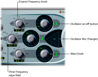
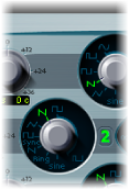
- Oscillator on/off buttons: Click the oscillator number to the right of each oscillator to activate or deactivate each oscillator independently. A green numeric button indicates an active oscillator. A gray numeric button denotes an inactive oscillator. Deactivating an oscillator saves computer processing power as you are not merely muting it—you are actually turning it off.
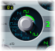
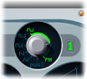
- Wave knobs: Sets the type of waveform that an oscillator generates. The waveform is responsible for the basic tonal color. See Using the ES2’s Basic Oscillator Waveforms.
- (Fine) Frequency value field: Used to fine-tune the oscillator frequency (pitch). The value display works as follows: the left numbers show the semitone setting, the right numbers show the cent (1 cent = 1/100th semitone) setting. These are denoted by an s or c to the right of the value. You can adjust these two values independently. For example, an oscillator with the value 12 s 30 c sounds an octave (12 semitones) and 30 cents higher than an oscillator with the value 0 s 0 c.
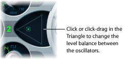
- Oscillator Mix (Triangle): Dragging the square icon in the Triangle cross-fades (sets the level relationships) between the three oscillators. See Setting the Oscillator Level Balance in the ES2.
Using the ES2’s Basic Oscillator Waveforms
All of the ES2 oscillators output a number of standard waveforms—sine, pulse, rectangular, sawtooth, and triangular waves—or, alternately, any of 100 Digiwaves (see Using Digiwaves in the ES2). The following table includes the basic waveforms:
Waveform | Basic tone | Comments |
|---|---|---|
Pulse/Rectangular | Nasal sounding | Great for reed instruments, synth blips, and basses |
Square | Hollow and woody sounding | Useful for basses, clarinets, and oboes. The pulse width of (Oscillator 2 and 3) square waveforms can be smoothly scaled between 50% and the thinnest of pulses. |
Sawtooth | Warm and even | Useful for strings, pads, bass, and brass sounds |
Triangle | Sweet sounding, softer than sawtooth | Useful for flutes and pad sounds. |
Sine | A pure tone | The sine wave of Oscillator 1 can be frequency modulated by Oscillator 2. This kind of modulation forms the basis of FM synthesis (see Using Frequency Modulation in the ES2). |
Oscillators 2 and 3 also offer the selection of:
A rectangular wave, synchronized to Oscillator 1.
A sawtooth wave, synchronized to Oscillator 1.
A ring modulator, which is fed by the output of Oscillator 1 and a square wave from Oscillator 2.
Colored noise for Oscillator 3 (see Using Noise in the ES2 (Oscillator 3 Only)).
Oscillator synchronization and ring modulation enable the creation of very complex and flexible harmonic spectra. The principles behind oscillator synchronization are described in Synchronizing the ES2 Oscillators. Ring modulation principles are discussed in Using Ring Modulation in the ES2.
Using Pulse Width Modulation in the ES2
You can alter the tonal color of rectangular waveforms by scaling the width of waveform pulses to any value. This is known as pulse width modulation.
The pulse width modulation features of the ES2 are extensive. As an example, if rectangular waves are chosen for all oscillators, you can simultaneously modulate the pulse width of Oscillator 1 and the synchronized pulse waves of Oscillator 2 (or the square wave of Oscillator 2’s ring modulator) and Oscillator 3.
Drag the waveform rotary control in the area highlighted in the image above.
Only Oscillators 2 and 3 allow you to define a “base” pulse width, prior to any pulse width modulation.
Choose Osc1Wave as the Target.
Choose LFO1 as the Source.
Adjust the modulation amount slider (a value of 0.12 is subtle, but sweet).
Choose a sine wave for LFO 1.
Adjust the LFO 1 Rate (0.160 Hz is nice for slow sweeps).
Modulating ES2 Oscillator Pulse Width with an LFO
Pulse width modulation (PWM) can be automatically controlled with appropriate settings in the router. A pulse wave (with PWM controlled by an LFO set to a sine wave) makes a single oscillator sound vivid, undulating, and overtone-rich. Sonically, this is similar to the sound of two slightly detuned, phasing oscillators, which is great for sustained bass and pad sounds.
The graphic below shows a pulse wave, with the pulse width modulated by an LFO. You can clearly see how the width of the pulses changes over time.
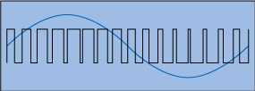
Note: Select the intensity and speed of the modulation with care, because the overall volume decreases, and slight detuning occurs, when the pulses become very narrow (below a width value of 10%).
Tip: Pulse width modulations via velocity-sensitive envelope generators sound very dynamic—a great effect that is especially suitable for percussive bass sounds.
Using Frequency Modulation in the ES2
The principle of frequency modulation (FM) synthesis was developed in the late 1960s and early 1970s by John Chowning. It was popularized by Yamaha’s range of DX synthesizers in the 1980s. The ES2 can’t be compared with the DX series in the discipline of pure FM synthesis, but it can certainly achieve some of the signature sounds of these instruments.
How Frequency Modulation Works
Stated simply, the frequency of one signal generator, or oscillator, is altered—modulated—by another signal generator. Positive values from the second generator increase the frequency of the first generator. Negative values decrease the frequency.
In a synthesizer, this type of modulation takes place in the audible range. Depending on the design of the instrument, you can hear the signals of either the first oscillator alone (being modulated by the other oscillator), or both oscillators. The interaction between the two generators alters the waveform signal of the first oscillator and introduces a number of new harmonics. This harmonic spectrum can then be used as the source signal for further sound processing, such as filtering, envelope control, and so on. See Frequency Modulation (FM) Synthesis for further information.
How Frequency Modulation Works in the ES2
In the ES2, the frequency of Oscillator 1 (with a sine wave chosen—11 o’clock position for the Wave knob) can be modulated by the output signal of Oscillator 2.
When Oscillator 2 outputs a positive signal, the frequency of Oscillator 1 increases.
When Oscillator 2 outputs a negative signal, the frequency of Oscillator 1 decreases.
The net effect of speeding up or slowing down the frequency of Oscillator 1 in each waveform cycle is a distortion of the basic wave shape. This waveform distortion also has the side benefit of introducing a number of new, audible harmonics.
Important: The impact of any frequency modulations you perform depends on both the frequency ratio and the modulation intensity of the two oscillators.
Adjust the Frequency (coarse and fine tune) parameter values of one, or both, oscillators.
Click (or drag) in the control range between the Sine and FM icons around the Oscillator 1 Wave knob. This determines the amount, or intensity, of frequency modulation.
Using Different ES2 Waveforms for FM Synthesis
The “pure” FM synthesis method uses a sine wave for both the first and second signal generator (both Oscillator 1 and 2 would be limited to generating a sine wave in the ES2 if you stuck with this approach).
The ES2, however, provides 100 Digiwaves and countless combinations of modulation intensities and frequency ratios that can be used for either oscillator. This provides a vast pool of harmonic spectra and tonal colors for you to experiment with—so it would be a shame if you don’t take advantage of these options!
Tip: The type of modulation that occurs can vary significantly when different waveforms are chosen for Oscillator 2—the modulating oscillator—in particular.
Using Ring Modulation in the ES2
Ring modulation is a powerful tool for the creation of inharmonic, metallic, bell-like sounds. The spectra resulting from its use are inharmonic at almost every frequency ratio. The ring modulator is a device that dates back to the early days of the synthesizer.
How a Ring Modulator Works
A ring modulator has two inputs. At the output you hear both the sum and difference frequencies of the input signals. If you ring modulate a sine oscillation of 200 Hz with a sine oscillation of 500 Hz, the output signal of the ring modulator will consist of a 700 Hz (sum) and a 300 Hz (difference) signal. Negative frequencies result in a change to the phase polarity of output signals.
How Ring Modulation Works in the ES2
You can set Oscillator 2 to output a ring modulator signal by choosing the Ring setting with the Oscillator 2 Wave knob. Feel free to experiment with different Frequency (main and fine tune) values for one, or both, oscillators.
The Oscillator 2 ring modulator is fed with the output signal of Oscillator 1 and a square wave—generated by Oscillator 2 itself. The pulse width of this square wave can be modulated (see Using Pulse Width Modulation in the ES2).
Tip: Use sawtooth and rectangular (pulse width modulated) input signals from Oscillators 1 and 2, respectively, to create a much more complex output signal. The use of these harmonically rich waveforms results in a number of extra sidebands becoming audible.
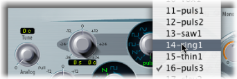
Using Digiwaves in the ES2
In addition to the basic synthesizer waveforms, all of the ES2 oscillators provide 100 additional waveforms, called Digiwaves. These are very short samples of the attack transients of various sounds and instruments.
Set the Wave knob to Sine (6 o’clock position), then do one of the following:
Control-click or right-click the Sine label, and choose a waveform from the pop-up menu.
Click-hold the Sine label and drag the mouse vertically.
Shift-click the menu, and type in a value, to select the Digiwave numerically.
Using Noise in the ES2 (Oscillator 3 Only)
The sonic palette of Oscillator 3 is bolstered by the inclusion of a noise generator, which can be activated by choosing the noise waveform. By default, Oscillator 3’s noise generator generates white noise.
White noise is defined as a signal that consists of all frequencies (an infinite number) sounding simultaneously, at the same intensity, in a given frequency band. The width of the frequency band is measured in Hertz. Sonically, white noise falls between the sound of the consonant “F” and breaking waves (surf). White noise is useful for synthesizing wind and seashore noises, or electronic snare drum sounds.
Emulating Detuned Analog Synthesizer Oscillators in the ES2
The Analog parameter is found towards the top left of the ES2 interface. It alters the pitch of each note—and the filter cutoff frequency—in a random fashion.
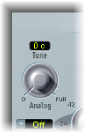
Much like polyphonic analog synthesizers, all three oscillators maintain their specific frequency deviation from each other, but the pitches of all three oscillators are randomly detuned by the same Analog amount. For example, if the Analog detuning is set to around 20%, all three oscillators (if used) will randomly drift by 20%.
Low Analog values can add a subtle richness to the sound.
Medium Analog values simulate the tuning instabilities of analog synthesizer circuitry, which can be useful in achieving that much sought-after “warmth” of analog hardware synthesizers.
High Analog values result in significant pitch instability, which can sound truly out of tune—but this may be perfect for your needs.
Note: If the ES2 is set to Mono or Legato keyboard mode, the Analog parameter is effective only when Unison is active. In this situation, Analog sets the amount of detuning between the stacked (unison) voices. If the Voices parameter is set to 1 and/or Unison is not activated, the Analog parameter has no effect. For more information about these parameters, see Choosing the ES2 Keyboard Mode (Poly/Mono/Legato).
Emulating Stretch Tuning in the ES2
The (coarse) Frequency knob of each oscillator allows you to tune Oscillators 1, 2, and 3 in semitones or octaves. The (fine tune) Frequency parameter allows you to fine-tune each oscillator in cents (1/100th of a semitone). Precise detuning between oscillators can result in beats, or phasing, between the oscillator frequencies. The higher the played frequency/pitch, the faster the phasing beats. High notes, therefore, may seem to be somewhat out of tune in comparison with lower notes.
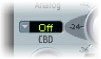
The CBD (Constant Beat Detuning) parameter—to the left of Oscillator 2’s Frequency knob—detunes the harmonics of the low-note frequencies in a ratio that is proportionate with the fundamental tone of the upper-note frequencies.
This is a very natural-sounding effect, common to acoustic pianos, which are intentionally tuned “out-of-tune” (from equal temperament). This is known as stretch tuning—and results in the upper and lower keyboard ranges being slightly out of tune with the center octaves but harmonically “in-tune” with each other.
Some Tips on Using Constant Beat Detuning
CBD can be used as a corrective tool to even out the beating between oscillators, or it can be used as a creative tool to emulate stretch tuning. The latter can be particularly important when you use an ES2 sound alongside an acoustic piano recording.
The CBD parameter offers five values: off, 25%, 50%, 75%, and 100%. If you choose 100%, the phasing beats are almost constant across the entire keyboard range. This value may, however, be too high, as the lower notes might be overly detuned at the point where the phasing of the higher notes feels right. Try lower CBD values in cases where the bass notes appear to be a little too far out of tune with the upper keyboard range.
The reference pitch for CBD is C3 (middle C): Its (de)tuning is constant, regardless of the chosen CBD value.
Setting the Oscillator Level Balance in the ES2
Dragging the square icon in the Triangle cross-fades—sets the level relationships—between the three oscillators. This is self-evident in use. If you move the square icon along one of the Triangle’s sides, it cross-fades between the two closest oscillators, and the third oscillator is muted.
Adjusting the ES2 Oscillator Start Point
The oscillators can either run freely or begin at the same phase position of their respective waveform cycles—each time the ES2 receives a note on message. You can set the desired behavior using the Osc Start (Oscillator Start) pop-up menu, found at the upper-right corner of the ES2 interface.

When Osc Start is set to free: The initial oscillator phase start point is random for each played note. This adds life to the sound. The downside is that the output level may differ each time a note is played, making the attack phase sound less punchy—even if the performance is identical each time—such as when the note is triggered by a MIDI region. This setting is useful when you are emulating the sounds typical of hardware analog synthesizers.
When Osc Start is set to soft: The initial oscillator phase starts at a zero crossing for each played note. This mimics the sonic character (and precision) that is typical of digital synthesizers.
When Osc Start is set to hard: The initial oscillator phase starts at the highest level in the waveform cycle for each played note. The extra “punch” that this setting can provide is audible only if the ENV3 Attack Time parameter is set to a low value—a very fast attack, in other words. This setting is highly recommended for electronic percussion and hard basses.
Note: Osc Start soft and hard result in a constant output level of the initial oscillator phase every time the sound is played back. This may be of particular importance when you use the Bounce function at close to maximum recording levels.
Synchronizing the ES2 Oscillators
Typical “oscillator sync” sounds tend toward the aggressive, screaming leads that synthesizer manufacturers like to talk about. The rectangular and sawtooth waveforms of Oscillators 2 and 3 feature a Sync option. When this parameter is turned on, the phase of Oscillator 2 or 3 is synchronized with Oscillator 1.
Every time Oscillator 1 starts a new oscillation phase, the synchronized oscillator (Oscillator 2 or 3) is also forced to restart its phase from the beginning. Between the waveform cycles of Oscillator 1, the waveform cycles of the synchronized oscillators run freely.
Envelope Modulation of the Synchronized Oscillator Frequency
Synchronized oscillator sounds are especially cool when the frequency of the synchronized oscillator is modulated by an envelope generator. This way, the number of phases within a section of the synchronization cycle constantly changes, resulting in corresponding changes to the frequency spectrum.