Working with Modulation in the ES2
The ES2 is equipped with a huge number of modulation sources and targets, making the ES2 a very flexible synthesizer that can generate extraordinary sounds that constantly evolve, sound like audio loops, or are just plain expressive to play. Reference tables that cover all modulation targets and sources are found at the end of this section.
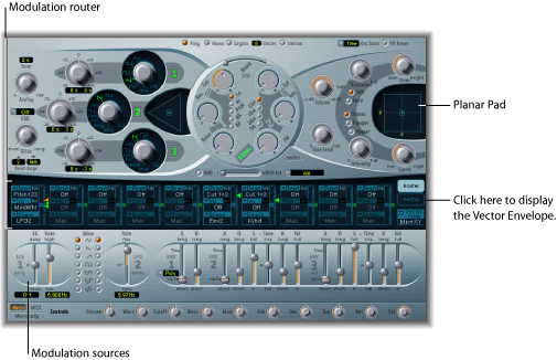
- Modulation router: The modulation router—or router, for short—links modulation sources such as the envelope, to modulation targets such as the oscillators and filters. The router features 10 modulation routings, arranged into columns. See Getting to Know the ES2’s Modulation Router.
- Modulation sources: The modulation sources include the LFOs and envelopes. See Getting to Know the ES2 LFOs and Getting to Know the ES2 Envelopes (ENV 1 to ENV 3).
- Vector Envelope: The Vector Envelope is an extremely sophisticated, loop-capable, multipoint envelope that can control the Planar Pad and Triangle (oscillator mix parameter). The Vector Envelope shares the space occupied by the modulation router and can be viewed by clicking the Vector Envelope button to the right of the router. See Getting to Know the ES2’s Vector Envelope.
- Planar Pad: The Planar Pad is a two-dimensional controller—which facilitates the simultaneous manipulation of two, freely assignable, parameters. It can be controlled with the Vector Envelope. See Using the ES2’s Planar Pad.
Getting to Know the ES2’s Modulation Router
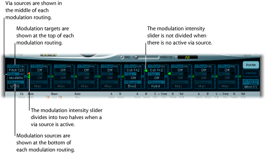
The modulation router—or router—spans the center of the ES2 interface. Click the Router button to view it if the Vector Envelope is displayed (these components share the same section of the interface). If you are new to synthesizer modulation routings, refer to the Synth Basics Modulation section.
Any modulation source can be connected to any modulation target—much like an old-fashioned telephone exchange or a studio patch bay.
The modulation intensity—how strongly the target is influenced by the source—is set with the vertical slider to the right of the modulation routing.
The intensity of the modulation can itself be modulated: The via parameter defines a further modulation source, which is used to control the modulation intensity. When via is active, you can specify upper and lower limits for the modulation intensity.
Ten such modulation routings of source, via, and target can take place simultaneously, in addition to routings that are hard-wired outside of the router. It does not matter which of the ten modulation routings you use.
You can even select the same target in several parallel modulation routings. You can also use the same sources and the same via controllers in multiple modulation routings.
Creating and Bypassing ES2 Modulation Routings
The following information applies to all ten modulation routings.
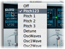
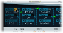
Click in the Target field. A pop-up menu of all available targets appears.
Click in the Source field. A pop-up menu of all available sources appears.
Choose the parameter you want to modulate.
Choose the parameter you want to use to modulate the target.
Vertically drag the arrowhead of the Intensity slider to the right of the modulation routing.
This sets a fixed modulation intensity.
Click the “b/p” button at the top right of the modulation routing beside the Target label.
The Bypass (b/p) parameter allows you to enable or disable individual modulation routings, without losing settings.
Using Via Sources to Control ES2 Modulation Intensity
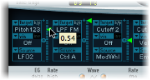
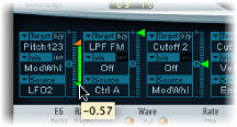
In a basic modulation routing comprised of a target and source, you can set a fixed modulation intensity by vertically dragging the arrowhead of the Intensity slider to the right of the routing. The slider value always defines a constant modulation intensity.
The intensity of the modulation can itself be modulated: The via parameter defines a further modulation source, which is used to control the modulation intensity. As soon as you choose a value other than off for “via,” the Intensity slider is divided into two halves. Each half has its own arrowhead.
The lower half defines the minimum modulation intensity, when the via controller—the modulation wheel, for example—is set to its minimum value.
The upper half defines the maximum modulation intensity when the via controller is set to its maximum value.
The area between the two slider halves defines the modulation range of the via controller.
Click in the Target field. A pop-up menu of all available targets appears.
Click in the Source field. A pop-up menu of all available sources appears.
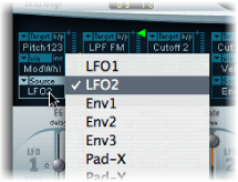
Click-hold in the via field to see a pop-up menu of all available sources.
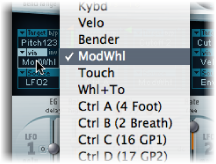
Choose the source you want to use for control of the modulation intensity.
Vertically drag the upper arrowhead of the Intensity slider (to the right of the modulation routing) to set the maximum modulation intensity.
Vertically drag the lower arrowhead of the Intensity slider to set the minimum modulation intensity.
Drag the range area between the two slider halves vertically.
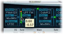
Both arrowheads will move simultaneously.
If this area is too small to be dragged, just drag an unused section of the Intensity slider “track” to move the area.
Click the little zero symbol beside the via label.
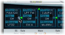
Click the via invert (inv) parameter to the right of the via label.
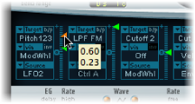
An ES2 Modulation Example
Imagine an ES2 sound with these settings:
- Target: Pitch123
- via: ModWheel
- Source: LFO1
- Modulation intensity: Slider position, set as desired
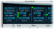
Pitch123 is the modulation target in this example.
The modulation source—LFO1—is used to modulate the frequency, or pitch, of all three oscillators (Pitch123).
You’ll hear a vibrato—a modulation of the pitch—at a speed determined by LFO 1’s Rate parameter.
The modulation intensity is controlled by the modulation wheel, the range of which is determined by the via parameter. This provides you with control over the depth of vibrato—pitch modulation—via the modulation wheel of your keyboard. This type of configuration is used in countless sound settings.
Getting to Know the ES2 LFOs
The ES2 features two multiwaveform LFOs. Both are available as sources in the router.
LFO 1 is polyphonic, which means that if it is used for any modulation of multiple voices, they will not be phase-locked. Furthermore, LFO 1 is key-synced: Each time you play a key, the LFO 1 modulation of this voice is started from zero.
To understand the nonphase-locked characteristic more fully, imagine a scenario where a chord is played on the keyboard. If LFO 1 is used to modulate pitch, for example, the pitch of one voice may rise, the pitch of another voice might fall, and the pitch of a third voice may reach its minimum value. As you can see, the modulation is independent for each voice, or note.
The key-sync feature ensures that the LFO waveform cycle always starts from zero, which results in consistent modulation of each voice. If the LFO waveform cycles were not synchronized in this way, individual note modulations would be uneven.
LFO 1 can also be faded in or out automatically, courtesy of a built-in envelope generator.
LFO 2 is monophonic, which means that the modulation is identical for all voices. For example, imagine a scenario where a chord is played on the keyboard. If LFO 2 is used to modulate pitch, the pitch of all voices in the played chord will rise and fall synchronously.
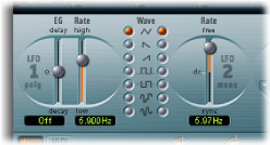
- LFO 1 EG slider: Controls the time it takes for the LFO modulation to fade in or fade out (see Using LFO 1’s Envelope Generator in the ES2).
- LFO 1 Wave buttons: This is where you choose the desired waveform for LFO 1. See Using ES2 LFO Waveforms for details on how to use them.
- LFO 2 Rate slider: This parameter defines the frequency—speed—of the LFO 2 modulation. See Setting LFO 2’s Rate in the ES2.
Using ES2 LFO Waveforms
The LFO 1 Wave buttons allow you to choose different waveforms for LFO 1. The table below outlines how these can affect your sounds.
Try using the waveforms while a modulation routing of Pitch123 (the pitch of all three oscillators) is engaged and running.
Waveform | Comments |
|---|---|
Triangle | Well suited for vibrato effects |
Sawtooth | Well suited for helicopter and space gun sounds. Intense modulations of the oscillator frequencies with a negative (inverse) sawtooth wave lead to “bubbling” sounds. Intense sawtooth modulations of lowpass filter cutoff and resonance creates rhythmic effects. The waveform can also be inverted, resulting in a different start point for the modulation cycle. |
Rectangle | Use of the rectangular waves will periodically switch the LFO between two values. The upper rectangular wave switches between a positive value and zero. The lower wave switches between a positive and a negative value set to the same amount above/below zero. An interesting effect can be achieved by modulating Pitch123 with a suitable modulation intensity that leads to an interval of a fifth. Choose the upper rectangular wave to do so. |
Sample & Hold | The two lower waveform settings of the LFOs output random values. A random value is selected at regular intervals, as defined by the LFO rate. The upper waveform steps between randomized values—rapid switches between values. At its lower setting the random wave is smoothed out, resulting in fluid changes to values. The term Sample & Hold (S & H) refers to the procedure of taking samples from a noise signal at regular intervals. The values of these samples are then held until the next sample is taken.Tip: A random modulation of Pitch123 leads to an effect commonly referred to as a random pitch pattern generator or sample and hold. Try using very high notes, at very high rates and high intensities—you’ll recognize this well-known effect from hundreds of science fiction movies! |
Using LFO 1’s Envelope Generator in the ES2
LFO 1 features a simple envelope generator, which is used to control the time it takes for the LFO modulation to fade in or fade out. At its center position, which can be accessed by clicking the middle mark, the modulation intensity is static—that is, no fade in or fade out will occur.
Choose a positive LFO 1 EG value to fade in the modulation.
The higher the value, the longer the delay time.
Choose a negative LFO 1 EG value to fade out the modulation.
The lower the slider is positioned onscreen, the shorter the fade out time.
LFO envelopes are most often used for delayed vibrato—many instrumentalists and singers intonate longer notes this way.
Place the LFO 1 EG slider at a position in the upper half (Delay) and modulate the Pitch123 target with the LFO1 source in the router.
Set a slight modulation intensity.
Select an LFO 1 Rate of about 5 Hz.
Choose the triangular wave as the LFO 1 waveform.
Tip: Chaotic and fast modulations of oscillator frequencies (target: Pitch123) by the LFO 1 source—with a delayed Sample&Hold waveform, a high Rate, and short fade out—is ideal for emulating the attack phase of brass instruments.
Setting LFO 2’s Rate in the ES2
LFO 2 is ideally suited for creating rhythmic modulation effects—that retain perfect synchronicity, even during project tempo changes.
The LFO 2 Rate parameter allows LFO 2 to run freely (in the upper half of the Rate slider range), or to be synchronized with the project tempo (in the lower half of the Rate slider range).
The rate is displayed in Hertz or rhythmic values (the latter when project tempo synchronization is active). Rates range from speeds of 1/64-notes to a periodic duration of 32 bars. Triplet and punctuated values are also available.
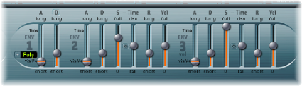
Getting to Know the ES2 Envelopes (ENV 1 to ENV 3)
The ES2 features three envelope generators per voice. They are abbreviated as ENV 1, ENV 2, and ENV 3, respectively, in the interface and router. In addition, the ES2 features the sophisticated Vector Envelope (see Getting to Know the ES2’s Vector Envelope).
Note: To learn more about the roots of the term “envelope generator” and its basic functionality, see Synthesizer Basics.
The parameters of ENV 2 and ENV 3 are identical. ENV 3 defines the changes in level over time for each note played. You can regard ENV 3 as being hard-wired to the router’s AMP modulation target.
Envelope Modulation of ES2 Filter Cutoff
Unlike many other synthesizers, the ES2 has no hard-wired connection between any of the envelope generators and the filter cutoff frequencies.
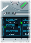
Set up a modulation routing as follows, in order to establish this type of modulation: Set target to Cutoff 1, Cutoff 2, or Cut 1+2. Set source to ENV 2, for example. After it is set as described, the slider to the right of the modulation routing will function as the filter’s EG Depth parameter.
Note: Both ENV 2 and ENV 3 are velocity sensitive, making it unnecessary to set via to Velo in the modulation routing; you can leave via off.
Getting to Know ENV 1 in the ES2
Although ENV 1 might appear to be rather poorly equipped at first glance, its handful of parameters are useful for a vast range of synthesizer functions.
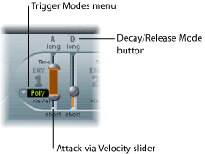
- Trigger Modes menu: You can define the trigger behavior of ENV 1 by choosing one of the following settings:
- Poly: The envelope generator behaves as you would expect on any polyphonic synthesizer: Every voice has its own envelope.
- Mono: A single envelope generator modulates all voices in the same way. All notes must be released before the envelope can be retriggered. If you play legato, or any key remains depressed, the envelope won’t restart its attack phase.
- Retrig: A single envelope generator modulates all voices in the same way. The envelope will be triggered by any key you strike, even when other notes are sustained. All sustained notes are identically affected by the retriggered envelope.
- Attack via Velocity slider: The Attack time slider is divided into two halves. The lower half defines the attack time when the keys are struck hard—at maximum velocity. The upper half defines the attack time at minimum velocity. Drag the area between the two slider halves to move them both simultaneously. If this area is too small to drag, click an unused portion of the slider, and drag vertically.
Setting Envelope 1 Decay or Release in the ES2
ENV 1 can be set to act as an envelope generator with either of the following: an Attack time and Decay time parameter or an Attack time and Release time parameter.

Click the D or the R above the right ENV 1 slider. The button label will change to reflect the mode that is activated.
- In Attack/Decay mode: The level will fall to zero after the attack phase has completed, whether or not the note is sustained. It will decay at the same speed—even if you release the key. The decay time is set with the D (Decay time) slider.
- In Attack/Release mode: The envelope level remains at its maximum after the attack phase is over, while the key remains depressed. Following the release of the key, the level decreases over the time period defined by the R (Release time) slider.
Getting to Know ENV 2 and ENV 3 in the ES2
The feature sets of ENV 2 and ENV 3 are identical, but it is always the task of ENV 3 to define the level of each note—to modulate the dynamic stage, in other words.
ENV 3 is, however, also available for simultaneous use as a source in the router. The envelope time parameters can also be used as modulation targets in the router.
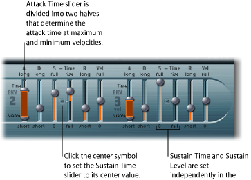
- Attack slider: Defines the length of time it takes for the level of a note to rise from an amplitude of zero to the set amplitude. The Attack time sliders of ENV 2 and ENV 3 are divided into two halves.
The lower half defines the attack time when the keys are struck hard, at maximum velocity. The upper half defines the attack time at minimum velocity. Drag the area between the two slider halves to move them both simultaneously. If this area is too small to be dragged, click in an unused portion of the slider and drag vertically.
- Decay slider: Determines the period it takes for the level of a held note to fall to the sustain level, after the attack phase has completed.
If the Sustain level parameter is set to its maximum value, the Decay parameter has no effect.
When the Sustain level is set to its minimum value, the Decay parameter defines the duration or fade-out time of the note.
- Sustain and Sustain Time sliders: There are two sustain parameters that interact with each other. One controls the sustain level, and the other controls the sustain time. See Using the Envelope 2 and 3 Sustain Parameters in the ES2.
- Vel (Velocity Sensitivity) slider: Determines the velocity sensitivity of the entire envelope. If set to maximum, the envelope will output its maximum level only when the keys are struck at maximum velocity. Softer velocities result in a corresponding change to the envelope levels—with a 50% velocity resulting in half-levels for each envelope-level parameter.
Using the Envelope 2 and 3 Sustain Parameters in the ES2
When the Sustain Time (rise) slider is set to its center value, the Sustain (S) Level slider behaves like the sustain parameter of any synthesizer ADSR envelope.
In this position, the Sustain (Level) slider defines the level that is sustained while the key remains depressed, following completion of the Attack time and Decay time phases.
The Sustain Time slider defines the time it takes for the level to rise from the Sustain level back to its maximum level—or to fall to zero:
Settings in the lower half of the Sustain Time slider range (fall) determine the time required for the level to decay from the sustain level to zero. The lower the slider position, the faster the sound level decays.
Settings in the upper half of its range (rise) determine the time required for the level to rise from the sustain level to its maximum value. The higher the slider position, the faster the sound level rises.
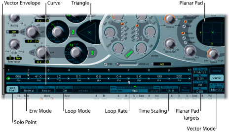
Getting to Know the ES2’s Vector Envelope
The Vector Envelope is a multipoint, loop-capable control source. Its sole purpose is to provide real-time control of square icon movements in the Triangle and the Planar Pad. The Vector Envelope shares the space occupied by the modulation router, and it can be viewed by clicking the Vector Envelope button to the right of the router.
Each voice is equipped with an independent Vector Envelope, which is triggered from its start point with every new keystrike (MIDI note-on message).
Conceptually, the Vector Envelope—and Planar Pad and Triangle—may seem somewhat strange, and perhaps a little intimidating, but a little experimentation on your part will reveal how easy these features are to use. Combining these facilities with other ES2 synthesis options enables you to create some truly unique sounds that are—quite literally—moving.
Turn off the Solo Point button (described on Setting the ES2 Vector Envelope Solo Point) to activate the Vector Envelope.
Turn on the Solo Point button to deactivate the Vector Envelope.
When Solo Point is turned on, only the currently selected Triangle and Planar Pad positions of the currently selected point are active.
Vector Envelope Control of the ES2’s Planar Pad and Triangle
The Vector Mode pop-up menu below the Vector Envelope button allows you to specify the target for the Vector Envelope—the Planar Pad and/or the Triangle.
- Off: The Vector Envelope does not control the Triangle or the Planar Pad. It is completely turned off. This allows you to manually set and control the square icons of the Triangle and the Planar Pad.
- Mix: The Vector Envelope controls the Triangle, but not the Planar Pad.
- XY: The Vector Envelope controls the Planar Pad, but not the Triangle.
- Mix+XY: The Vector Envelope controls both the Planar Pad and the Triangle.
An Overview of ES2 Vector Envelope Points, Times, and Loops
The Vector Envelope time axis runs from left to right.
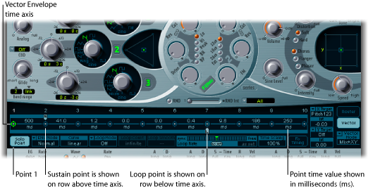
Up to 16 points can be displayed on the time axis (10 are shown in the figure above). Each point can control the square icon positions of the Triangle and the Planar Pad (as described in Vector Envelope Control of the ES2’s Planar Pad and Triangle).
The points are numbered sequentially—from left to right—along the time axis.
There are always at least three points: Point 1 is the start point, point 2 is defined as the Sustain point, and point three is the end point.
Any point can be declared the Sustain point. If a played note is held for a sufficient length of time and there’s no loop engaged, any envelope movement will stop when the Sustain point is reached. The Sustain point value is maintained until the key is released—until the MIDI note-off command.
Any point can be declared the Loop point. The looped area spans the time between the Sustain point and Loop point. In between these points you can create further points that describe the movements of the square icons in the Planar Pad and Triangle.
Selecting, Creating, and Deleting ES2 Vector Envelope Points
The more points you set, the more complex the movements that can be performed.
Click to select. Once selected, you can freely edit the point.
Shift-click between two existing points.
The segment that previously existed between the two old points is divided at the clicked position. The sum of the two new segment times is equal to the time of the original undivided segment. This ensures that following points retain their absolute time positions. Existing square icon positions in the Triangle and Planar Pad are fixed, thus ensuring that newly created points don’t affect any previously defined movements.
Control-click it.
Reverting to Default ES2 Vector Envelope Point Values
On occasion you may want to revert to the default values of a point. This is done directly in the Triangle or the Planar Pad:
Option-click the Triangle. The square icon is set to the center position of the Triangle.
All oscillators are set to output the same level.
Option-click the Planar Pad.
The square icon is set to the center position of the Planar Pad. Both axis values are set to zero.
Setting the ES2 Vector Envelope Solo Point
The Solo Point button basically turns off the Vector Envelope. If the Solo Point button is activated, no dynamic modulations are generated by the Vector Envelope. In this scenario, the currently visible square icon positions of the Triangle and Planar Pad are permanently in effect. These square icon positions match the currently selected Vector Envelope point.
If you select another Vector Envelope point by clicking it, the square icon positions in the Triangle and Planar Pad will update to reflect your selection. If the Solo Point button is turned on, the newly selected point will become the Solo point.
Note: You can independently switch off Vector Envelope modulation of the Planar Pad by setting Vector Mode to off, as described in Vector Envelope Control of the ES2’s Planar Pad and Triangle.
Setting the ES2 Vector Envelope Sustain Point
As mentioned earlier, any point can be declared the Sustain point. Assuming that the played note is held long enough and there’s no loop engaged, any envelope movement will stop when this Sustain point is reached. The Sustain point value is maintained until the key is released—until the MIDI note-off command.
Click in the turquoise strip above the desired point.
The Sustain point is indicated by an S between the point and its number shown on the turquoise strip.
Setting Up ES2 Vector Envelope Loops
The Vector Envelope can run in one-shot mode—as long as the note is sustained; it can be set to repeat a specific number of times; or it can repeat indefinitely—much like an LFO modulation. You can achieve repetitions by using the loop functions.
Although the loop parameters may remind you of the loop parameters available for samples, there are significant differences between them. The Vector Envelope only supplies control signals that are used to move the square icon positions of the Triangle and Planar Pad. The audio output of the ES2 is not looped in any way.
Setting the Loop Point
Any point can be declared the Loop point. Provided that the note is held for a suitable length of time, portions of the envelope can be repeated, or looped.
The looped area spans the time between the Sustain point and the Loop point. In-between these points you can define several points that describe square icon movements in the Triangle and the Planar Pad.
Click in the turquoise strip below the desired point.
A Loop point is indicated by an L in the strip below.
Note: To see and define the Loop point, Loop Mode must be activated (see “Setting the Vector Envelope Loop Mode” below).
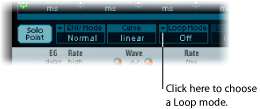
Setting the ES2 Vector Envelope Loop Mode
You can choose from the following Vector Envelope Loop modes: Off, Forward, Backward, and Alternate.
- Off: When Loop Mode is set to Off, the Vector Envelope runs in one-shot mode from beginning to end—if the note is held long enough to complete all envelope phases. The other loop parameters are disabled.
- Forward: When Loop Mode is set to Forward, the Vector Envelope runs from the beginning to the Sustain point—then begins to periodically repeat the section between the Sustain point and the Loop point—in a forward direction.
- Backward: When Loop Mode is set to Backward, the Vector Envelope runs from the beginning to the Sustain point—then begins to periodically repeat the section between the Sustain point and the Loop point—in a backward direction.
- Alternate: When Loop Mode is set to Alternate, the Vector Envelope runs from the beginning to the Sustain point—then periodically switches to the Loop point, then back to the Sustain point—alternating between backward and forward directions.
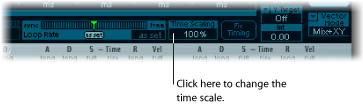
Setting the ES2 Vector Envelope Loop Rate
Just as every LFO has a speed, or rate, parameter, the loop can be set to cycle at a defined speed. The Vector Envelope Loop Rate can also be synchronized with the project tempo.
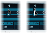
Drag the green indicator in the center of the Loop Rate bar to the left or right.
Drag vertically in the value field “as set” (shown in the figure below).
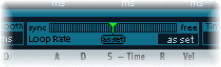
- As set: If you switch the Loop Rate to “as set,” the loop cycle length will equal the sum of the times between the sustain and Loop points. Click the field labeled “as set” below the Rate slider to select it.
- Rhythmic: If you set the Loop Rate to one of the rhythmic values (sync) by dragging the Loop Rate indicator towards the left half of the slider, the loop rate will follow the project tempo. You can choose from 32 bars up to a 64th triplet note value.
- Free: You can also set a free Loop Rate by dragging the Loop Rate indicator towards the right half of the slider (free). The value indicates the number of cycles per second.
Note: If Loop Rate is not switched to “as set,” and Loop Mode (Forward, Backward, or Alternate) is active, the times of points between the Loop and Sustain points and the Loop Smooth value are shown as a percentage of the loop duration, rather than in milliseconds.
Making Smooth ES2 Vector Envelope Loop Transitions
When Loop Mode is set to Forward or Backward, there will inevitably be a moment when a transition from the Sustain point to the Loop point occurs. You can use the Loop Smooth parameter to even out the transition, thus avoiding abrupt position changes.
If the Loop Rate parameter is set to Sync or Free, the loop smoothing time is displayed as a percentage of the loop cycle duration.
If the Loop Rate parameter is “as set,” the loop smoothing time is displayed in milliseconds (ms).
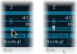
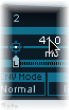
Setting the ES2 Vector Envelope Release Phase Behavior
There are two release phase options in the Env Mode menu: Normal and Finish.
Using the Normal ES2 Vector Envelope Mode
If the Env Mode menu is set to Normal, the release phase—the phase after the Sustain point—begins as soon as you release the key (note off). In other words, the release phase will start from the Vector Envelope point where you released the key.
The following behaviors apply:
If looping is turned off and the Vector Envelope reaches the Sustain point, the Sustain point value will be retained for as long as you hold a key.
If looping is turned on and the Loop point is positioned before the Sustain point, the loop will cycle for as long as you hold a key.
If looping is turned on and the Loop point is positioned after the Sustain point, the Vector Envelope loop will continue to cycle until the overall release phase of the sound, as determined by the ENV 3 Release parameter, has completed.
Using the Finish ES2 Vector Envelope Mode
If the Env Mode menu is set to Finish, the Vector Envelope does not immediately commence the release phase when you release the key. Rather, it plays all points for their full duration until the end point is reached, regardless of whether you hold the key or release it.
The following behaviors apply:
If looping is turned off, the Sustain point is ignored. The Vector Envelope will complete all points up to the end point, regardless of whether you hold the key or release it.
If looping is turned on, the Vector Envelope will play all points until it reaches the Loop point, and then play the loop until the end point is reached. It does not matter if the Loop point is positioned before or after the Sustain point.
If looping is turned on, and Loop Count is set to a value other than “infinite,” the Vector Envelope will continue on to the subsequent points—following completion of the specified number of loop repetitions. If Loop Count is set to “infinite,” the points after the loop are irrelevant. See ES2.
Choosing ES2 Vector Envelope Point Transition Shapes
The Curve parameter defines the shape of the transition from point to point. You can choose from nine convex and nine concave shapes. There are also two unusual curve forms, “hold+step” and “step+hold,” which allow stepped modulations.
- step+hold: This curve jumps at the beginning of the transition.
- hold+step: This curve jumps at the end of the transition.
Note: You can use “hold+step” to create stepped vector grooves—with up to 15 steps.
Setting ES2 Vector Envelope Times
With the exception of the first point, which is tied to the beginning of each played note, every point has a Time parameter. This parameter defines the period of time required for the position indicator to travel from the point that preceded it. The times are normally displayed in milliseconds (ms).
Click the numerical value and drag vertically.
Note: Changing a time value alters the absolute time positions of all subsequent points.
Control-drag the Time parameter to increase or decrease the time required to reach the following point. The time setting of the ensuing point is simultaneously adjusted—by a corresponding amount. This ensures that the adjacent and all following points retain their absolute time positions.
Time Scaling the ES2’s Vector Envelope
You can stretch and compress the entire Vector Envelope. This is extremely useful if you want to double the Vector Envelope’s speed, for example. Rather than halving the time values of every point, you can set the Time Scaling parameter above the ENV3 Attack slider to 50%.
The Time Scaling parameter ranges from 10% to 1000%. It is scaled logarithmically.
If the Loop Rate is “as set,” scaling also affects the loop.
If the Loop Rate is set to a free or synced value, the setting is not affected by the Time Scaling parameter.
ES2 Fix Timing—Normalizing Time Scaling and the Loop Rate
Clicking the Fix Timing button (to the right of the Time Scaling parameter) multiplies the Time Scaling value by all time parameters, and Time Scaling will be reset to 100%. There will be no audible difference. This is simply a normalizing procedure, similar to the Normalizing function in the Region parameter box.
In cases where Loop Rate is set to a synced value, clicking Fix Timing will switch the Loop Rate to “as set,” thus preserving the absolute rate.
Using the ES2 Vector Envelope Shortcut Menu
A number of Vector Envelope commands and functions can be accessed by right-clicking anywhere in the Vector Envelope. This will launch the pop-up menu shown below.
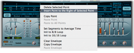
Choose any item in the menu to perform the command or function.
Using the ES2’s Planar Pad
The Planar Pad has two axes—X and Y. The X axis is on the horizontal plane and the Y axis is on the vertical plane.
You can modulate one user-defined parameter with the X value and another user-defined parameter with the Y value, allowing you to use the mouse like a joystick.
The X and Y axes have positive and negative value ranges. When you drag the square icon, the values of both axes are continuously transmitted.
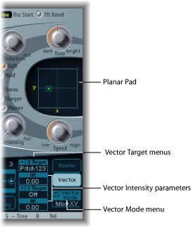
Choosing a Vector Target—Modulation Destinations
The Vector X and Vector Y Target menus determine which parameter is modulated by square icon movements in the Planar Pad. The modulation targets are identical to those in the router. See ES2 Modulation Target Reference for descriptions.
The position of the square icon in the Planar Pad is also available in the router, as the Pad-X and Pad-Y source and via options. See ES2 Modulation Source Reference and Using Via Sources to Control ES2 Modulation Intensity.
Setting the Vector Intensity—Defining the Modulation Intensity
The maximum intensity, sensitivity, and polarity of the modulation is set with the Vector X Int and Vector Y Int parameters.
Drag vertically in the Vector X and Y Int fields.
Use a negative value to invert the modulation polarity.
ES2 Modulation Target Reference
The following targets are available for real-time modulation.
ES2 Oscillator Targets
The table below includes all oscillator-related modulation targets.
Target | Comments |
|---|---|
Pitch123 | Modulates the frequencies (pitch) of all three oscillators. If you select an LFO as the source, this target leads to siren or vibrato sounds. Select one of the envelope generators with zero attack, short decay, zero sustain, and short release as the source for tom and kick drum sounds. |
Pitch 1 | Modulates the frequency (pitch) of Oscillator 1. Slight envelope modulations can make the amount of detuning change over time, when Oscillator 1 is sounding in unison with another (unmodulated) oscillator. This also applies to the other Pitch targets and is particularly useful for synthesizer brass sounds. |
Pitch 2 | Modulates the frequency (pitch) of Oscillator 2. |
Pitch 3 | Modulates the frequency (pitch) of Oscillator 3. |
Detune | Controls the amount of detuning between all three oscillators. The sensitivity of all pitch modulation targets is determined by the modulation intensity. This is scaled as per the lists below, allowing you to create very delicate vibrati in the cent range (1/100 semitone), and huge pitch jumps by octaves.
This leads to the following rules of thumb for modulation intensity values.
|
OscWaves | Depending on the waveforms set in the three oscillators, this target can be used to modulate:
OscWaves affects all oscillators simultaneously. For further information about the effects of these modulations, see Using Pulse Width Modulation in the ES2, Using Frequency Modulation in the ES2, Using Noise in the ES2 (Oscillator 3 Only), and Using Digiwaves in the ES2. |
Osc1Wave | Depending on the waveform selected for Oscillator 1, you can control the pulse width of rectangular and pulse waves, the amount of frequency modulation, or the position of the Digiwave. Note: In classic FM synthesizers the amount of FM is controlled in real time by velocity-sensitive envelope generators. Select one of the ENVs as the source for such sounds. |
Osc2Wave | The same as Osc1Wave, except that Oscillator 2 does not feature FM. Note that pulse width modulation also works with both the synchronized rectangular and ring modulated rectangular waves. |
Osc3Wave | Oscillator 3 is the same as Osc1Wave and Osc2Wave except that it does not feature FM or ring modulation. Oscillator 3 features noise, the color of which can be modulated with this parameter. |
OscWaveB | The transitions between Digiwaves during a wavetable modulation (where you switch between different Digiwaves) are always smooth. You can use the OscWaveB target to continuously modulate the shape of the transitions from smooth to hard. This target applies to all oscillators. |
Osc1WaveB | If wavetable modulation is active for a Digiwave (using the Osc1Wav target), you can use this target to modulate the shape of the transition. When you are frequency-modulating Oscillator 1, the Osc1WaveB target offers much higher FM intensities than either the Osc1 FM or the Osc1Wave targets. |
Osc2WaveB | The same as above for a Digiwave using the Osc2Wav target. |
Osc3WaveB | The same as above for a Digiwave using the Osc3Wav target. |
SineLev1 | SineLevl (Sine Level) allows the sine wave level of Oscillator 1 to be modulated. The parameter defines the level of the first partial tone of Oscillator 1. See Thickening the ES2’s Sound with Sine Level. |
OscLScle | OscLScle (Osc Level Scale) modulates the levels of all three oscillators simultaneously. A modulation value of 0 mutes all oscillators, whereas a value of 1 raises the gain of the entire mix by 12 dB. The modulation is applied before the overdrive stage, allowing for dynamic distortions. |
Osc1Levl | (Osc 1 Level) allows modulation of Oscillator 1’s level. |
Osc2Levl | (Osc 2 Level) allows modulation of Oscillator 2’s level. |
Osc3Levl | (Osc 3 Level) allows modulation of Oscillator 3’s level. |
ES2 Filter Targets
The table below includes all filter-related modulation targets.
Target | Comments |
|---|---|
Cutoff 1 | Modulates the Cutoff Frequency parameter of Filter 1. See Using the ES2 Filter Cutoff and Resonance Parameters. |
Resonance 1 | (Reso 1) Modulates the Resonance parameter of Filter 1. |
Cutoff 2 | Modulates the Cutoff Frequency parameter of Filter 2. |
Resonance 2 | (Reso 2) Modulates the Resonance parameter of Filter 2. |
LPF FM | Determines the intensity of the lowpass filter frequency modulation (LPF FM) of Filter 2—with a sine wave (at the same frequency as Oscillator 1). This parameter is described in Modulating Filter 2’s Frequency in the ES2. |
Cut 1+2 | Modulates the cutoff frequency of both filters in parallel. This is like applying the same modulation to Cutoff 1 and Cutoff 2 in two modulation routings. |
Cut1inv2 | Cut1inv2 (Cutoff 1 normal and Cutoff 2 inverse) simultaneously modulates the cutoff frequencies of the first and second filters inversely (in opposite directions). Put another way, when the first filter’s cutoff frequency is rising, the cutoff of the second filter will fall—and vice versa. In cases where you have combined Filter 1, defined as a highpass filter, and Filter 2 in serial mode, both act as a bandpass filter. Modulating the Cut1 inv 2target will result in a modulation of the bandpass filter’s bandwidth in this scenario. |
Filter Blend | (FltBlend) modulates the Filter Blend parameter. See Getting to Know the ES2 interface. |
Other ES2 Targets
The table below includes all other modulation targets.
Target | Comments |
|---|---|
Amp | This target modulates the dynamic stage, or level of voices. If you select Amp as the target and modulate it with an LFO as the source, the level will change periodically, and you will hear a tremolo. |
Pan | This target modulates the panorama position of the sound in the stereo or surround spectrum. Modulating Pan with an LFO will result in a stereo or surround tremolo (auto panning). In unison mode, the panorama positions of all voices are spread across the entire stereo or surround spectrum. Nevertheless, pan can still be modulated, with positions being moved in parallel. The extended Surround Range parameter defines the angle range resulting from modulation values. For example, if pan is modulated by the maximum amount of an LFO (using a sawtooth waveform), a Surround Range value of 360 results in circular movements of the voice output. |
Diversity | This parameter (available only in surround instances of the ES2) allows you to dynamically control how much the voice output is spread across the surround channels. Negative values reduce this effect. |
LFO1Asym | (LFO1 Asymmetry) can modulate the selected waveform of LFO 1. If a square wave, it changes pulse width. If a triangle wave, it sweeps between triangle and sawtooth. If a sawtooth wave, it shifts its zero crossing. |
LFO1Curve | This target modulates the waveform smoothing of the square and random wave. If the LFO is using a triangle or sawtooth wave, it changes between convex, linear, and concave curves. |
Scaled ES2 Modulation Targets
All of the following modulation targets result in a scaled modulation, which means that the target parameter value will be multiplied by the modulation value. This works as follows: a modulation value of 0.0 results in no change, a modulation value of +1.0 equals a 10x multiplication, and a modulation value of −1.0 equals a multiplication by 0.04.
Target | Comments |
|---|---|
LFO1Rate | This target modulates the frequency (rate) of LFO 1. You can automatically accelerate or slow down LFO 1’s rate by modulating the LFO1Rate target with one of the envelope generators (ENV) or with LFO2. |
Env2Atck | (Envelope 2 Attack) modulates the Attack time of the second envelope generator. |
Env2Dec | (Envelope 2 Decay) modulates the Decay time of the second envelope generator. In cases where you’ve selected Env2Dec as the target and Velocity as the source, the duration of the decaying note is dependent on how hard you strike the key. Selecting Keyboard as the source will result in higher notes decaying more quickly (or slowly). |
Env2Rel | Env2Rel (Envelope 2 Release) modulates the Release time of the second envelope generator. |
Env2Time | Env2Time (Envelope 2 All Times) modulates all of ENV2’s time parameters: Attack, Decay, Sustain, and Release times. |
Env3Atck | Env3Atck (Envelope 3 Attack) modulates the Attack time of ENV3. |
Env3Dec | Env3Dec (Envelope 3 Decay) modulates the Decay time of ENV3. |
Env3Rel | Env3Rel (Envelope 3 Release) modulates the Release time of ENV3. |
Env3Time | Env3Time (Envelope 3 All Times) modulates all ENV3 time parameters: Attack, Decay, Sustain, and Release times. |
Glide | This target modulates the duration of the Glide (portamento) effect. If you modulate Glide, with Velocity selected as the source, the speed of the keystrike determines the time it takes for the played notes to reach the target pitch. |
ES2 Modulation Source Reference
The following modulation sources are available:
Source | Comment |
|---|---|
LFO1 | LFO 1 is used as a source. |
LFO2 | LFO 2 is used as a source. |
ENV1 | Envelope Generator 1 is used as a source. |
ENV2 | Envelope Generator 2 is used as a source. |
ENV3 | Envelope Generator 3 is used as a source. Envelope Generator 3 always controls the level of the overall sound. |
Pad-X, Pad-Y | Define the axes of the Planar Pad as modulation sources for the selected modulation target. See Using the ES2’s Planar Pad and Getting to Know the ES2’s Vector Envelope. |
Max | Max sets the value of this source to +1. This offers interesting options for controlling the modulation intensity with all possible via values. |
Kybd | Kybd (Keyboard) outputs the keyboard position (the MIDI note number). The center point is C3 (an output value of 0). Five octaves below and above, an output value of −1 or +1, respectively is sent. Modulate the Cut 1+2 target with the Kybd source to control the cutoff frequencies of the filters with the keyboard position—as you play up and down the keyboard, the cutoff frequencies change. A modulation intensity of 0.5 proportionately scales cutoff frequencies with keyboard note pitches. |
Velo | Velocity sensitivity serves as a modulation source. |
Bender | The pitch bend wheel serves as a bipolar modulation source. This is also true when the Bend Range parameter of the oscillators is set to 0. |
ModWhl | The modulation wheel serves as a modulation source.Note: For most standard applications, you’ll probably use the wheel as the via controller. Traditionally, it is used to control the intensity of periodic LFO modulations. Used here, it can be employed for direct, static modulations, such as controlling both filter cutoff frequencies (Target = Cut 1+2). |
Touch | Aftertouch serves as a modulation source. The ES2 reacts to poly pressure (polyphonic aftertouch).Note: If you set the Target to Cut 1+2, the cutoff frequencies will rise and fall, depending on how firmly you press a key on your touch-sensitive MIDI keyboard—after the initial keystrike. |
Whl+To | Both the modulation wheel and aftertouch serve as modulation sources. |
MIDI Controllers A-F | MIDI controllers available in the router are named Ctrl A–F and can be assigned to arbitrary controller numbers. Please see the Using Macro Controls and Assigning Controllers in the ES2. |
RndN01 | RndNO1 (Note On Random1) outputs a random modulation value between −1.0 and 1.0, that changes when a note is triggered or retriggered. The (random) note-on modulation remains constant throughout the note duration, until the next note-on trigger.Note: There is no value change when playing legato while in legato mode. |
RndN02 | RndNO2 (Note On Random 2) behaves like Note On Random1, but it glides, rather than steps, to the new random value—using the Glide time (inclusive of modulation). It also differs from Note On Random 1 in that the random modulation value changes when playing legato while in legato mode. |
SideCh | SideCh (Side Chain modulation) uses a side chain signal as a modulation (trigger) signal. The side chain source can be selected in the Side Chain menu in the upper gray area of the plug-in window. It is fed to the internal envelope follower, which creates a modulation value based on the current side chain input signal level. |
ES2 Modulation Via Source Reference
The following sources may be used to control the modulation intensity.
Via source | Comment |
|---|---|
LFO1 | The modulation undulates at the speed and waveform of LFO 1, which controls the modulation intensity. |
LFO2 | The modulation undulates at the speed and waveform of LFO 2, which controls the modulation intensity. |
ENV1 | ENV1 controls the modulation intensity. |
ENV2 | ENV2 controls the modulation intensity. |
ENV3 | ENV3 controls the modulation intensity. |
Pad-X, Pad-Y | Both axes of the Planar Pad are available as viasources as well, enabling you to control modulation intensities with them. |
Kybd | Kybd (Keyboard) outputs the keyboard position (the MIDI note number). The center point is C3 (an output value of 0). Five octaves below and above, an output value of −1 or +1, respectively, is sent. If you select Pitch123 as the target, modulate it with the LFO1 source, and select Keyboard as the via value, the vibrato depth will change, depending on the key position. Put another way, the vibrato depth will be different for notes higher or lower than the defined Keyboard position. |
Velo | If you select Velo (Velocity) as the via value, the modulation intensity will be velocity sensitive—modulation will be more or less intense depending on how quickly (how hard) you strike the key. |
Bender | The pitch bend wheel controls the modulation intensity. |
ModWhl | If you select ModWhl (Modulation Wheel) as the via value, the modulation intensity will be controlled by your MIDI keyboard’s modulation wheel. |
Touch | If you select Touch (Aftertouch) as the via value, the modulation intensity will be touch sensitive—modulation will be more or less intense depending on how firmly you press the key of your touch-sensitive MIDI keyboard after the initial keystrike (aftertouch is also known as pressure sensitivity). |
Whl+To | Both the modulation wheel and aftertouch control the modulation intensity. |
MIDI Controllers A-F | MIDI controllers available in the router are named Ctrl A–F, rather than Expression, Breath, and General Purpose 1–4 (MIDI Control Change Messages 16 to 19 are also known as General Purpose Slider 1/2/3/4). These can be assigned to arbitrary controller numbers via menus in the Controller Assignments section at the bottom of the interface (press the MIDI button to view menus A to F). |
RndN01 | RndNO1 (Note On Random1) outputs a random modulation intensity value between −1.0 and 1.0, which changes when a note is triggered or retriggered. The random note-on modulation remains constant throughout the note duration, until the next note-on trigger.Note: There is no value change when playing legato while in legato mode. |
RndN02 | RndNO2 (Note On Random 2) behaves like Note On Random1, but it glides, rather than steps, to the new random intensity value—using the Glide time (inclusive of modulation). It also differs from Note On Random 1 in that the random modulation value changes when playing legato while in legato mode. |
SideCh | SideCh (Side Chain modulation) uses a side chain signal as a modulation intensity (trigger) signal. The side chain source can be selected in the Side Chain menu in the upper gray area of the plug-in window. It is fed to the internal envelope follower, which creates a modulation value based on the current side chain input signal level. |