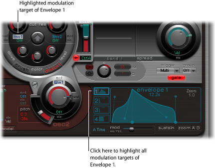
Working with Modulation in Ultrabeat
Most sound parameters can be controlled dynamically (modulated) in Ultrabeat. Ultrabeat provides two LFOs, four envelope generators, velocity, and four freely definable MIDI controllers as modulation sources. The setting of modulation routings follows a universal principle that works as follows:
Ultrabeat’s modulation routings feature three key elements:
- The modulation target: The synthesizer parameter that you want to modulate.
- The modulation source: The parameter that modulates the target.
- The via source: A secondary modulation source that can influence the intensity of the first modulation source.
Note: You can freely use the same sources and the same via controllers in multiple modulation routings.
Mod and Via Modulations in Ultrabeat
You can modulate a sound parameter using an adjustable value—the modulation depth or intensity—with the “mod” parameter. You can choose between two LFOs, four envelope generators, and Max as sources for this modulation.
Via allows you to further tailor the modulation effect. The depth of the first modulation (“mod”) can be modulated by a separate, independent source. The intensity of this effect is set with the “via” parameter. The sources for via modulations include velocity and four freely definable MIDI controllers.
A typical via modulation usage example would be increasing a pitch sweep as you play at higher velocities. To this end, you would use:
An envelope (Env) as the “mod” source for the pitch of an oscillator
Velocity (Vel) as the via source
The harder the key is played, the higher (in pitch) it will sound—which is ideal for synthesized tom-tom sounds, for example.
Ultrabeat Modulation Examples
Consider the following example to better understand how this works:
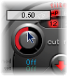
The default Cut (Cutoff) parameter value is 0.50. No modulation source has been selected in either the blue “mod” or green “via” menu (both are Off) in the image below.
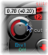
When a modulation source is selected in the “mod” menu (Env 1 in the image below), the ring around the rotary knob is activated. Drag in the ring to set the desired value (0.70 in the example) for the Cut parameter—when affected by the “mod” source.
Note: Exact values are shown in the help tags when adjusting various parameters.
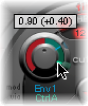
As soon as a modulation source is selected in the “via” menu (Ctrl A in the image below), a movable slider appears on the “mod” ring. Drag this slider to set the maximum modulation value that can be reached through use of the via source (0.90 in this example).
So much for the settings. What do the markings found around the Cut knob mean, and what is happening to the sound?
The “mod” and “via” controls indicate the minimum and maximum values that the modulated parameter can attain, in comparison to the default value.
In the example, the Cut(off) frequency of the filter is set to a default value of 0.50. The “mod” source (Env 1) drives the Cut value up from 0.50 to 0.70 during the attack phase and back down to 0.50 during the decay phase.
When the via source (Ctrl A) is introduced, the following interplay occurs: when Ctrl A is at its minimum value, nothing changes; Cutoff continues to be modulated between values of 0.50 and 0.70 by the envelope (Env 1). A maximum value for Ctrl A causes the envelope generator to vary the parameter between the values of 0.50 (the default Cut value) and 0.90 (the via amount).
You can see at a glance the degree of maximum influence on basic parameters by the mod and via modulation sources—the area between the mod and via points shows the amount that the modulation depth can be further altered by the via modulation source. In the example, the Cutoff can reach values between 0.70 and 0.90 depending on the value being sent by Ctrl A.
Here’s another example:
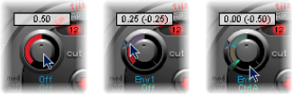
Cutoff is again set to 0.50, Env 1 now drives the value down to 0.25, and a maximum Ctrl A value reduces the Cutoff frequency down to 0.
The example below illustrates the simplicity and speed of Ultrabeat’s modulation options:

In this example, the modulation intensity of Env 1, which affects Cutoff, is controlled with the dynamics of the performance (Vel). The secondary via modulation also controls its direction. Try this setting in Ultrabeat to create some extremely interesting sounds.
Creating an Ultrabeat Modulation Routing
The following applies to all parameters that offer “mod” (and “via”) modulation options.
Click the “mod” label of the desired parameter to open the “mod” pop-up menu.
Choose one of the modulation source settings in the menu:
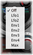
The Off setting deactivates the “mod” routing, and the “mod” control can no longer be adjusted. In this situation, no “via” modulation can occur either, because “via” no longer has a modulation target, and the “via” control disappears.
The Env settings set one of the envelope generators as modulation source
The Max setting produces a static modulation at maximum level. When the “mod” value is set to Max, the “via” parameter is routed directly to the modulation target. This way, velocity can be used as a direct modulation source, even though Vel is not available as a source in the “mod” menu.
Tip: You can also set up an external MIDI fader unit with Ctrl A, B, C, or D (see Using Ultrabeat MIDI Controllers A-D). You can then use the Max menu item to route the respective via source—Ctrl A, B, C, or D—to the parameter you’d like to control with one of the faders on your MIDI fader box.
If you want to assign a via source, click “via” to open the “via” pop-up menu.
Choose Vel or one of the parameters from Ctrl A through Ctrl D.
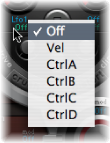
Vel represents velocity.
Ctrl A to Ctrl D are four continuous controllers that can be assigned to four external MIDI controllers. These assignments are made in the MIDI Controller Assignments area at the upper-right edge of the Ultrabeat window. The assignments apply to all sounds in the current Ultrabeat plug-in instance.
Adjust the “mod” and “via” controls as desired.
Using Ultrabeat MIDI Controllers A-D
The MIDI Controller Assignments area at the upper edge of the Ultrabeat window enables you to assign any MIDI controller shown in the menus to each of the four controller slots: Ctrl A, B, C, or D.

These assignments enable external MIDI controller hardware—such as sliders, knobs, aftertouch, or the modulation wheel of your MIDI keyboard—to control via modulation sources in Ultrabeat.
Open the desired control menu (Ctrl A–D), and choose the controller name or number that you want to use from the list.
Open the desired control menu, and choose the -Learn- menu item.
Move the desired controller on your MIDI keyboard or controller.
Note: If no suitable MIDI message is received within 20 seconds, the selected control reverts to the previous value/assignment.
Getting to Know the Ultrabeat LFOs
Two identical LFOs are available as modulation sources in the “mod” menu.
LFO is the abbreviation forlow frequency oscillator. The LFO signal is used as a modulation source. In an analog synthesizer, the LFO frequency generally ranges between 0.1 and 20 Hz, which is outside the audible frequency spectrum. Therefore, this type of oscillator is used only for modulation.
Note: The speed of the LFO in Ultrabeat can reach up to 100 Hz, which affords a number of possibilities that analog synthesizers simply don’t offer.
The parameters for both Ultrabeat LFOs are described below. You can freely adjust LFO 1 and LFO 2 independently of each other.
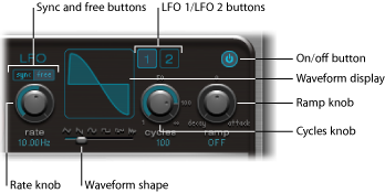
- LFO 1 and 2 buttons: Select the corresponding LFO, allowing independent parameter adjustments for each.
- On/Off button: Activates or deactivates the selected LFO.
- Sync/Free buttons: The LFO speed (Rate) can be set independently (Free) or synchronized (Sync) to the host application tempo. Click either button to activate the corresponding mode.
- Rate knob: Determines the speed of the LFO. Depending on the Free/Sync setting, the rate is displayed in Hertz or rhythmic values—the latter when project tempo synchronization is active. Rates range from speeds of 1/64 notes through to a periodic duration of 32 bars. Triplet and punctuated values are also available.
- Waveform Shape slider (and display): Determines the shape of the LFO waveform. Drag the slider from left to right to morph the waveform from a triangle, to a sawtooth, sine, square, and finally a rectangular wave shape—including all variations in-between. At the far right position, the LFO produces random waveforms. The graphical display shows the current LFO waveform shape.
- Cycles knob and field: Determines the number of times that the LFO waveform runs through. See Using Ultrabeat’s LFO Waveform Cycles Parameter.
- Ramp knob and field: Controls the time it takes for the LFO modulation to fade in or fade out. The Ramp value is displayed in milliseconds in its parameter field.
Turn Ramp to the right to set the Attack time of the LFO.
Turn Ramp to the left to set the Decay time.
At the middle position, Ramp has no effect on the LFO.
Using Ultrabeat’s LFO Waveforms
The Waveform Shape slider allows you to choose different waveforms for both LFOs. The table below outlines how these can affect your sounds. In-between waveform shapes will result in hybrid waveforms and hybrid behaviors.
Waveform | Comments |
|---|---|
Triangle | Well suited for vibrato effects |
Sawtooth | Well suited for helicopter and space gun sounds. Intense modulations of oscillator pitch with a sawtooth wave lead to “bubbling” sounds. Intense sawtooth modulations of lowpass filter cutoff and resonance create rhythmic effects. |
Sine | Ideal for smooth, even modulations. Its position on the Waveform Shape slider enables you to smoothly morph between sawtooth and square/rectangular waves. |
Square and Rectangle | Use of the square/rectangular waves will periodically switch the LFO between two values. The right-hand rectangular wave switches between a positive value and zero. The left-hand rectangular wave switches between a positive and a negative value set to the same amount above/below zero. |
Sample & Hold | The right-hand waveform on the Waveform Shape slider outputsrandom values. A random value is selected at regular intervals, as defined by the LFO rate. The termSample & Hold (S & H) refers to the procedure of taking samples from a noise signal at regular intervals. The values of these samples are thenheld until the nextsample is taken. Tip: A random modulation of oscillator pitch leads to an effect commonly referred to as arandom pitch pattern generator orsample and hold. Try using very high notes, at very high rates and high intensities—you’ll recognize this well-known effect from hundreds of science fiction movies! |
Using Ultrabeat’s LFO Waveform Cycles Parameter
An LFO normally oscillates continuously. On percussive signals it can, however, be interesting to limit the LFO cycles (repetitions of the entire waveform) to a defined number. Ultrabeat allows you to set the number of LFO cycles with the Cycles parameter. After completing the defined number of cycles, the LFO stops oscillating.
Tip: Try small Cycles parameter values, with the LFO source used to control the Volume (Level) of one or both oscillators. This will create typical drum flams or hand claps.
The range of Cycles parameter values extends from 1 to 100. Turn the knob to its maximum value (all the way to the right) to create an infinite number of cycles (standard LFO behavior). A Cycle value of 1 allows the LFO to function as an additional, albeit simple, envelope generator.
The Cycles parameter can also determine whether the LFO (waveform) is started from the beginning, at a 0-crossing point, with each note trigger, or whether it simply continues oscillating.
A Cycles value of Inf (Infinity) forces the LFO to run freely. It is not reset by incoming MIDI note on messages.
When Cycles is set to values under 100, the LFO will be reset by each new MIDI note on message (Note On Reset).
It’s really a question of taste as to whether or not you choose to trigger an LFO cycle from the same spot or just allow it to oscillate freely, regardless of phase. The random element of free-running LFOs can make many sounds fatter. This, however, can be at the expense of a percussive attack—which is not ideal for many drum sounds.
Note: You can, of course, use minor shifting of the LFO phase—with the Cycle value set to Infinity—to your advantage, adding an analog character to a drum sound, for example.
Getting to Know the Ultrabeat Envelopes (Env 1 to Env 4)
Further modulation sources available to you in the “mod” menu include the envelope generators.
Note: The roots of the term “envelope generator” and its basic functionality are described in The Attack, Decay, Sustain, and Release (ADSR) Envelope Controls.
Ultrabeat features four identically specified envelope generators per voice. They are abbreviated as Env 1 to Env 4. In addition to potential use as a modulation source (in the “mod” menus of various sound parameters), Env 4 is permanently connected to the Voice Volume parameter. In other words, each Ultrabeat drum sound has a hard-wired volume envelope generator—namely, Env 4.
The default behavior of the envelope generators is known as theone shot envelope mode: after a key is pressed (note on message), the envelopes run their course, regardless of how long the note is held. This setting is ideal for percussive signals because it emulates the natural behavior of acoustic percussion instruments.
For special cases, such as sustained pad or cymbal sounds, you can activate a sustain mode where the envelopes take the lengths of the played notes into account.
Editing Ultrabeat’s Envelopes Graphically
Ultrabeat’s envelope display provides a unique envelope design, consisting of Bezier curves in which two segments—attack and decay—constitute the entire envelope.
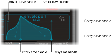
In the envelope graphic, you can see various handles (junction points) of two different sizes.
Both of the larger handles on the x-axis (the horizontal, or time axis at the bottom) control the attack and decay times, respectively. A vertical line extends up from the first of the two handles (attack), and divides the envelope into an attack and decay phase.
Both segments each have two small curve handles. You can drag these in any direction to deform the contour of the envelope and freely shape its amplitude.
You can also directly drag anywhere on the curve itself to reshape the envelope.
Using Ultrabeat’s Envelope Parameters
In order to edit envelope parameters, you first need to select one of the four envelopes with buttons 1 through 4. After this is done, the parameters of the corresponding envelope can be changed in the envelope display window.
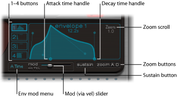
- Buttons 1–4: Used to choose one of the four envelopes. Only the selected envelope can be edited. The button frame of the chosen envelope is highlighted, and the envelope display immediately updates to reflect your selection.
- Attack Time handle: Defines the period of time the envelope needs to reach its maximum value after receiving a note on message. This period is called theattack phase.
- Decay Time handle: Defines the period of time the envelope needs to fall back to a 0 amplitude, after it has reached its maximum value (defined in the attack phase).
Note: You can freely change the time and shape of the envelope in the attack or decay phase. See Editing Ultrabeat’s Envelopes Graphically.
- Zoom scroll field: Resizes the visible contents of the envelope display when you drag horizontally.
- Env “mod” menu: Determines the modulation target (either the time or shape of the envelope attack or decay phase) by velocity. Choices are A Time, A Shape, D Time, or D Shape.
- “Mod” (via vel) slider: Determines the intensity of velocity modulation of the target specified in the Env “mod” menu.
When you modulate Shape, low velocity values make the envelope sag. Higher values make the envelope bulge.
When you modulate Time, high velocity values reduce the length of the envelope segment. Lower velocity values increase the length of the envelope segment.
- Sustain button: When active, displays a red handle (and vertical line) on the x-axis. This can be moved horizontally—but only within the envelope decay phase. The amplitude that the envelope reaches at the Sustain junction point is retained until the MIDI note is released.
Note: If the Sustain button is not activated, the envelope functions in one-shot mode, and the note length (MIDI note-off command) is disregarded.
- Zoom (to fit) button: Enlarges the envelope to fill the entire width of the envelope display, making it easier to adjust junction points and curves.
Note: When the Zoom function is active, the decay handle can be dragged beyond the right-hand edge of the envelope display area, in order to lengthen the decay time. After you release the mouse button, the envelope graphic is automatically resized to fit the display area.
- Zoom A/D buttons: Shows only the attack (A) or decay (D) phase across the entire width of the envelope display. This facilitates more accurate edits to envelope shapes, even down to millisecond values.