Ringshifter
The Ringshifter effect combines a ring modulator with a frequency shifter effect. Both effects were popular during the 1970s, and are currently experiencing something of a renaissance.
The ring modulator modulates the amplitude of the input signal using either the internal oscillator or a side-chain signal. The frequency spectrum of the resulting effect signal equals the sum and difference of the frequency content in the two original signals. Its sound is often described as metallic or clangorous. The ring modulator was used extensively on jazz rock and fusion records in the early 1970s.
The frequency shifter moves the frequency content of the input signal by a fixed amount and, in doing so, alters the frequency relationship of the original harmonics. The resulting sounds range from sweet and spacious phasing effects to strange robotic timbres.
Note: Frequency shifting should not be confused with pitch shifting. Pitch shifting transposes the original signal, leaving its harmonic frequency relationship intact.
Getting to Know the Ringshifter Interface
The Ringshifter interface consists of six main sections.
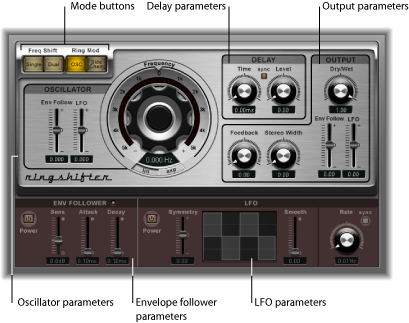
- Mode buttons: Determine whether the Ringshifter operates as frequency shifter or ring modulator See Setting the Ringshifter Mode.
- Oscillator parameters: Use these to configure the internal sine wave oscillator, which modulates the amplitude of the input signal—in both frequency shifter modes and the ring modulator OSC mode. See Using the Ringshifter’s Oscillator.
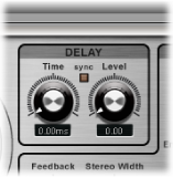
- Delay parameters: Use these to delay the effect signal. See Using the Ringshifter’s Delay.
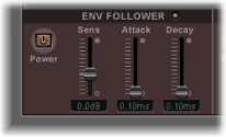
- Envelope follower parameters: The oscillator frequency and output signal can be modulated with an envelope follower. See Modulating the Ringshifter with the Envelope Follower.
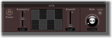
- LFO parameters: The oscillator frequency and output signal can be modulated with an LFO. See Modulating the Ringshifter with the LFO.
- Output parameters: The output section of the Ringshifter includes a feedback loop and controls to set the stereo width and amount of the dry and wet signals. See Controlling the Ringshifter Output Parameters.
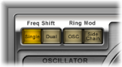
Setting the Ringshifter Mode
The four mode buttons determine whether the Ringshifter operates as a frequency shifter or as a ring modulator.
Using the Ringshifter’s Oscillator
In both frequency shifter modes and the ring modulator OSC mode, the internal sine wave oscillator is used to modulate the amplitude of the input signal.
In the frequency shifter modes, the Frequency parameter controls the amount of frequency shifting (up and/or down) applied to the input signal.
In the ring modulator OSC mode, the Frequency parameter controls the frequency content (timbre) of the resulting effect. This timbre can range from subtle tremolo effects to clangorous metallic sounds.
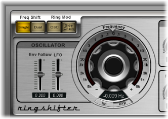
- Lin(ear) and Exp(onential) buttons: Switch the scaling of the Frequency control:
- Exp(onential): Exponential scaling offers extremely small increments around the 0 point, which is useful for programming slow-moving phasing and tremolo effects.
- Lin(ear): Linear scaling resolution is even across the entire control range.
Modulating the Ringshifter with the Envelope Follower
The oscillator Frequency and Dry/Wet parameters can be modulated with the internal envelope follower—and the LFO (see Modulating the Ringshifter with the LFO). The oscillator frequency even allows modulation through the 0 Hz point, thus changing the oscillation direction.
The envelope follower analyzes the amplitude (volume) of the input signal and uses this to create a continuously changing control signal—a dynamic volume envelope of the input signal. This control signal can be used for modulation purposes.
Modulating the Ringshifter with the LFO
The oscillator Frequency and Dry/Wet parameters can be modulated with the LFO—and the envelope follower (see Modulating the Ringshifter with the Envelope Follower). The oscillator frequency even allows modulation through the 0 Hz point, thus changing the oscillation direction. The LFO produces continuous, cycled control signals.
Controlling the Ringshifter Output Parameters
The output parameters are used to set the balance between the effect and input signals and also to set the width and feedback of the Ringshifter.
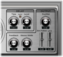
- Feedback knob and field: Sets the amount of the signal that is routed back to the effect input. Feedback adds an edge to the Ringshifter sound and is useful for a variety of special effects. It produces a rich phasing sound when used in combination with a slow oscillator sweep. Comb filtering effects are created by using high Feedback settings with a short delay time (less than 10 ms). Use of longer delay times, in conjunction with high Feedback settings, creates continuously rising and falling frequency shift effects.