Working with Space Designer’s Envelope and EQ Parameters
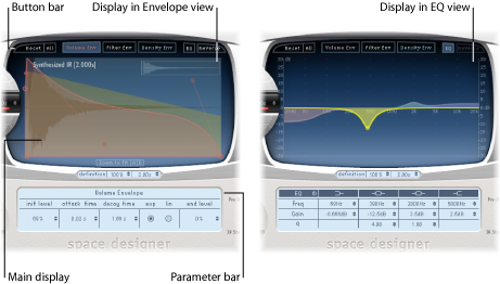
Space Designer’s main interface area is used to show and edit envelope and EQ parameters. It consists of three components: the button bar at the top, the main display, and the parameter bar.
The button bar is used to choose the current view/edit mode.
The main display shows, and allows you to graphically edit, either the envelope or the EQ curve.
The parameter bar displays, and allows you to numerically edit, either the envelope or the EQ curve.
Using Space Designer’s Button Bar
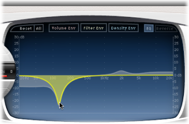
The button bar is used to switch the main display and parameter bar between envelope and EQ views. It also includes buttons that reset the envelopes and EQ or reverse the IR.

- Volume Env button: Displays the volume envelope in the foreground of the main display. The other envelope curves are shown as transparencies in the background. See Working with Space Designer’s Volume Envelope.
- Filter Env button: Displays the filter envelope in the foreground of the main display. The other envelope curves are shown as transparencies in the background. See Working with Space Designer’s Filter.
- Density Env button: Displays the density envelope in the foreground of the main display. The other envelope curves are shown as transparencies in the background. See Working in Space Designer’s Synthesized IR Mode.
- EQ button: Displays the four-band parametric EQ in the main display. See Working with Space Designer’s EQ.
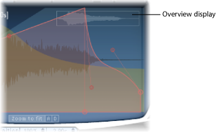
Zooming and Navigating Space Designer’s Envelope View
When displaying envelopes, the main display offers the following zoom and navigation parameters (not shown in EQ view).
Setting Space Designer’s Envelope Parameters
You can edit the volume and filter envelopes of all IRs and the density envelope of synthesized IRs. All envelopes can be adjusted both graphically in the main display and numerically in the parameter bar.
Whereas some parameters are envelope-specific, all envelopes consist of the Attack Time and Decay Time parameters. The combined total of the Attack Time and Decay Time parameters is equal to the total length of the synthesized or sampled impulse response, unless the Decay time is reduced. See Setting Impulse Response Lengths in Space Designer).
The large nodes are value indicators of the parameters shown in the parameter bar below—Init Level, Attack Time, Decay Time, and so on. If you edit any numerical value in the parameter bar, the corresponding node moves in the main display.
Drag the node in one of the available directions.
Two arrows are shown when you move the cursor over any node in the main display, indicating possible movements.
Drag the envelope curve in the main display.
Drag the small nodes attached to a line for fine adjustments to envelope curves. These nodes are tied to the envelope curve itself, so you can view them as envelope handles.

Working with Space Designer’s Volume Envelope
The volume envelope is used to set the reverb’s initial level and adjust how the volume will change over time. You can edit all volume envelope parameters numerically, and many can also be edited graphically (see Setting Space Designer’s Envelope Parameters).
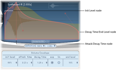
- Init Level field: Sets the initial volume level of the impulse response attack phase. It is expressed as a percentage of the full-scale volume of the impulse response file. The attack phase is generally the loudest point of the impulse response. Set Init Level to 100% to ensure maximum volume for the early reflections.
- End Level field: Sets the end volume level. It is expressed as a percentage of the overall volume envelope.
If set to 0%, you can fade out the tail.
If set to 100%, you can’t fade out the tail, and the reverb stops abruptly (if the end point falls within the tail).
If the end time falls outside the reverb tail, End Level has no effect.
Using Space Designer’s Density Envelope
The density envelope allows you to control the density of the synthesized impulse response over time. You can adjust the density envelope numerically in the parameter bar, and you can edit the Init Level, Ramp Time, and End Level parameters using the techniques described in Setting Space Designer’s Envelope Parameters.
Note: The density envelope is available only in Synthesized IR mode.
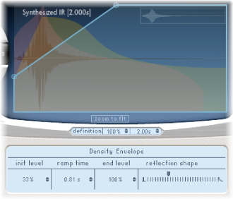
- Reflection Shape slider: Determines the steepness (shape) of the early reflection clusters as they bounce off the walls, ceiling, and furnishings of the virtual space. Small values result in clusters with a sharp contour, and large values result in an exponential slope and a smoother sound. This is handy when recreating rooms constructed of different materials. Reflection Shape, in conjunction with suitable settings for the envelopes, density, and early reflection will assist you in creating rooms of almost any shape and material.
Working with Space Designer’s EQ
Space Designer features a four-band EQ comprised of two parametric mid-bands plus two shelving filters (one low shelving filter and one high shelving filter). You can edit the EQ parameters numerically in the parameter bar, or graphically in the main display.
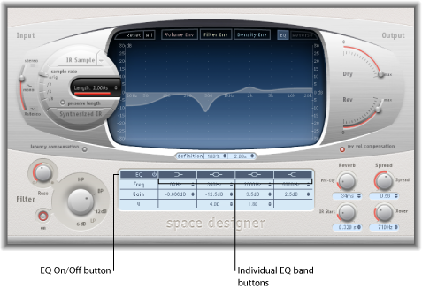
- EQ On/Off button: Enables or disables the entire EQ section.
- Individual EQ band buttons: Enable or disable individual EQ bands.
- Frequency fields: Set the frequency for the selected EQ band.
- Gain fields: Adjust the gain cut or boost for the selected EQ band.
- Q fields: Set the Q factor for the two parametric bands. The Q factor can be adjusted from 0.1 (very narrow) to 10 (very wide).
Enable the EQ and one or more bands with the EQ On/Off and EQ band buttons in the top row of the parameter bar.
Drag the cursor horizontally over the main display. When the cursor is in the access area of a band, the corresponding curve and parameter area is automatically highlighted and a pivot point is displayed.
Drag horizontally to adjust the frequency of the band.
Drag vertically to increase or decrease the Gain of the band.
Vertically drag the (illuminated) pivot point of a parametric EQ band to raise or lower the Q value.