Using the ES2 Filters
The ES2 features two discrete, and different, filters.
Filter 1 can operate as a lowpass, highpass, bandpass, band reject, or peak filter.
Filter 2 is a lowpass filter that offers variable slopes (measured in dB/octave).
Details on all filter parameters are covered in the following sections.
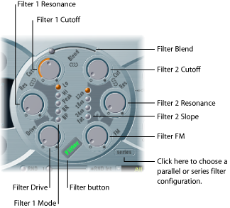
- Filter button: Activates or deactivates the entire filter section of the ES2. Deactivating the filter section makes it easier to hear adjustments to other sound parameters, because the filters always heavily affect the sound. Disabling the filters also reduces processor load. If the Filter label is green, the filters are engaged. If gray, the filters are disabled.
- Filter Configuration button: Switches between a parallel or series filter configuration. See Choosing a Series or Parallel Filter Configuration in the ES2.
- Filter Blend slider: Sets the balance between Filter 1 and Filter 2. See Filter Blend: Cross-Fading Between the ES2 Filters.
- Filter 1 Mode buttons: These buttons switch Filter 1 between lowpass, highpass, bandpass, band reject, or peak filter types. See Choosing Filter 1’s Mode in the ES2 (Lo, Hi, Peak, BR, BP).
- Filter 2 Slope buttons: These buttons switch Filter 2 between different slopes. See Setting Filter 2’s Slope in the ES2.
- Cutoff and Resonance: The Cutoff and Resonance knobs determine the cutoff frequency and resonance behavior of each filter. See Using the ES2 Filter Cutoff and Resonance Parameters.
- Filter Drive knob: Overdrives the filter, which affects each voice independently. See Overdriving the ES2 Filters.
- Filter FM knob: Modulates the Filter 2 Cutoff parameter with the Oscillator 1 frequency. See Modulating Filter 2’s Frequency in the ES2.
Choosing a Series or Parallel Filter Configuration in the ES2
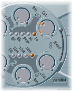
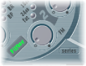
Click the Parallel/Series button to switch between a parallel and series filter routing. When either is chosen, the entire circular filter element of the ES2 user interface rotates, and the positions and direction of the filter controls clearly indicate the signal flow. The button name also changes in each mode.
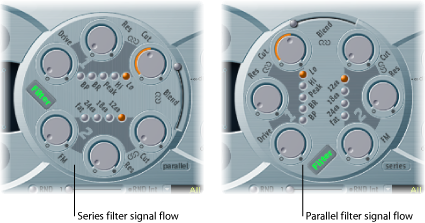
In the figure to the left, the filters are cabled in series. This means that the signal of all oscillators (combined at the Oscillator Mix Triangle) passes through the first filter, and then this filtered signal passes through Filter 2—if Filter Blend (see below) is set to 0, the middle position. The output signal of Filter 2 is then sent to the input of the dynamic stage (Amplifier section).
In the figure to the right, the filters are cabled in parallel. If Filter Blend is set to 0, you’ll hear a 50/50 mix of the source signal—routed via Filter 1 and Filter 2. The output signals of the two filters are then sent to the input of the dynamic stage.
Filter Blend: Cross-Fading Between the ES2 Filters
You can use the Filter Blend slider to cross-fade between the two filters when cabled in parallel. Filter Blend can have a significant effect on the ES2 signal flow. See The Impact of Filter Blend on the ES2 Signal Flow.

When Filter Blend is set to its top position, you’ll only hear Filter 1.
If Filter Blend is set to its lowest position, you’ll only hear Filter 2.
In between these positions, the filters are cross-faded.
You can also cross-fade the filters when they are cabled in series. In this scenario, the distortion—controlled by the Drive parameter—also needs to be considered, as this can be positioned either before or in-between the filters, depending on the Filter Blend setting you choose.
The Impact of Filter Blend on the ES2 Signal Flow
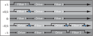
Regardless of whether parallel or series filter configurations are chosen, a Filter Blend setting of −1 results in only Filter 1 being audible. A Filter Blend setting of +1 will limit audibility to Filter 2.
The figures illustrate the signal flow between the Oscillator Mix stage (the Triangle) and the dynamic stage. The signal flow through the filters and the filter overdrive circuit (the Drive parameter) are dependent on the Filter Blend setting.
Use positive values for Filter Blend to partially bypass Filter 1.
Use negative values for Filter Blend to partially bypass Filter 2.
When zero or positive Filter Blend values are used, there is only one overdrive circuit for both filters.
Use of negative Filter Blend values introduces another overdrive circuit, which distorts the output signal of the oscillator mix stage before it is fed into the first filter.
If Drive is set to 0, no distortion occurs.
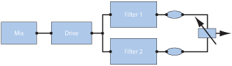
In a parallel configuration, the overdrive/distortion circuit—the Drive parameter—is always wired after the oscillator mix stage—the Triangle—and before the filters. The filters receive a mono input signal from the output of the overdrive circuit. The outputs of both filters are mixed to mono via Filter Blend.
Choosing Filter 1’s Mode in the ES2 (Lo, Hi, Peak, BR, BP)
Filter 1 can operate in several modes, allowing specific frequency bands to be filtered (cut away) or emphasized.

Select one of the following buttons to choose a filter mode for Filter 1:
- Lo (lowpass): This filter type allows frequencies that fall below the cutoff frequency to pass. When set to Lo, the filter operates as a lowpass filter. The slope of Filter 1 is fixed at 12 dB/octave in Lo mode.
- Hi (highpass): This filter type allows frequencies above the cutoff frequency to pass. When set to Hi, the filter operates as a highpass filter. The slope of Filter 1 is fixed at 12 dB/octave in Hi mode.
- Peak: Filter 1 works as a peak filter. This allows the level in a frequency band to be increased. The center of the frequency band is determined by the Cutoff parameter. The width of the band is controlled by the Resonance parameter.
- BR: (band rejection):The frequency band directly surrounding the cutoff frequency is rejected, whereas the frequencies outside this band can pass. The Resonance parameter controls the width of the rejected frequency band.
- BP (bandpass): The frequency band directly surrounding the cutoff frequency is allowed to pass. All other frequencies are cut. The Resonance parameter controls the width of the frequency band. The bandpass filter is a two-pole filter with a slope of 6 dB/octave on each side of the center frequency of the band.
Setting Filter 2’s Slope in the ES2
Most filters do not completely suppress the portion of the signal that falls outside the frequency range defined by the Cutoff parameter. The slope, or curve, chosen for Filter 2 expresses the amount of rejection below the cutoff frequency in decibels per octave.

Filter 2 offers three different slopes: 12 dB, 18 dB, and 24 dB per octave. The steeper the slope, the more severely the level of signals below the cutoff frequency are affected in each octave.
The Fat setting also provides 24 dB per octave of rejection but features a built-in compensation circuit that retains the “bottom end” of the sound. The standard 24 dB setting tends to make lower end sounds somewhat “thin.” See Getting to Know the ES2 Oscillators.
Using the ES2 Filter Cutoff and Resonance Parameters
In every lowpass filter (in the ES2:Lo mode for Filter 1. Filter 2 is a lowpass filter), all frequency portions above the cutoff frequency are suppressed, or cut off, hence the name. If you’re new to synthesizers and the concepts behind filters, see Synthesizer Basics.
The Impact of Cutoff Frequency on the ES2 Signal
The Cutoff Frequency (Cut) parameter controls the brilliance of the signal.
In a lowpass filter, the higher the cutoff frequency is set, the higher the frequencies of signals that are allowed to pass.
In a highpass filter, the cutoff frequency determines the point where lower frequencies are suppressed and only upper frequencies are allowed to pass.
In a bandpass/band rejection filter, the cutoff frequency determines the center frequency for the bandpass or band rejection filter.
The Impact of Resonance on the ES2 Signal
The Resonance (Res) parameter emphasizes or suppresses portions of the signal above or below the defined cutoff frequency.
In a lowpass filter, Resonance emphasizes or suppresses signals below the cutoff frequency.
In a highpass filter, Resonance emphasizes or suppresses signals above the cutoff frequency.
In bandpass/band rejection filters, resonance emphasizes or suppresses the portions of the signal—the frequency band—that surround the defined frequency, set with the Cutoff Frequency parameter.
Controlling Cutoff and Resonance Simultaneously in the ES2
Changing the Cutoff and Resonance controls at the same time is essential to the creation of expressive synthesizer sounds.
Drag one of the three chain symbols in the ES2 filter section.
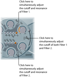
The chain between Cut and Res of Filter 1 controls both the resonance (drag horizontally) and cutoff frequency (drag vertically) simultaneously.
The chain between Cut and Res of Filter 2 controls both the resonance (drag horizontally) and cutoff frequency (drag vertically) simultaneously.
The chain between Filter 1 Cut and Filter 2 Cut controls the cutoff frequency of Filter 1 (drag vertically) and Filter 2 (drag horizontally) simultaneously.
Using Flt Reset to Drive the ES2 Filters to Self Resonance
If you increase the filter Resonance parameter to higher values, the filter will begin to internally feed back and, as a consequence, will begin to self-resonate. This self-resonance results in a sine oscillation—a sine wave—that is actually audible.
To start this type of oscillation, the filter requires a trigger. In an analog synthesizer, this trigger can be the noise floor, or the oscillator output. In the digital domain of the ES2, noise is all but eliminated. Therefore, when the oscillators are muted there is no input signal routed to the filter.
Turn on the Filter Reset button in the upper-right corner of the ES2 interface.

When engaged, each note starts with a trigger that makes the filter resonate immediately.
Using the ES2’s Fat Parameter to Compensate for High Resonance Values
Increasing the Resonance value results in a rejection of bass—low frequency energy—when you are using lowpass filters.
Turn on the Fat(ness) button—below the other filter slope buttons—to compensate for this side-effect and to obtain a richer sound.
Overdriving the ES2 Filters
The filters are equipped with separate overdrive modules. Overdrive intensity is defined by the Drive parameter.

If the filters are connected in parallel, the overdrive circuit is placed before the filters.
If the filters are connected in series, the position of the overdrive circuits is dependent on the Filter Blend parameter—as described in Filter Blend: Cross-Fading Between the ES2 Filters.
The ES2 filter Drive parameter affects each voice independently. When every voice is overdriven individually—like having six fuzz boxes for a guitar, one for each string—you can play extremely complex harmonies over the entire keyboard range. They’ll sound clean, without unwanted intermodulation effects spoiling the sound.
Furthermore, appropriate Drive parameter settings lead to a different tonal character for the following reason: The way analog filters behave when they are overdriven forms an essential part of the sonic character of a synthesizer. Each synthesizer model is unique in the way its filters behave when overdriven. The ES2 is very flexible in this area, allowing tonal colors that range from the most subtle fuzz to the hardest of distortions.
Tip: As Filter 2 can cut away the overtones introduced by the distortion, the Drive parameter can be seen and used as another tool for deforming oscillator waveforms.
Modulating Filter 2’s Frequency in the ES2
The Filter 2 cutoff frequency can be modulated by the sine wave of Oscillator 1, which is always generated, even when the oscillator is switched off. The level of this sine signal can be mixed in at the output stage with the Sine Level parameter (see Thickening the ES2’s Sound with Sine Level).
The effect of such filter modulations in the audio spectrum is unpredictable, but the results tend to remain harmonic if you avoid high modulation intensity values. The FM parameter is used to define the intensity of this filter frequency modulation.
Note: Don’t confuse this filter frequency modulation with the oscillator FM feature (Oscillator 1 is modulated by Oscillator 2, as described in Using Frequency Modulation in the ES2). If Oscillator 1 is frequency-modulated by Oscillator 2, it does not influence the sine wave signal used to modulate the cutoff frequencies.
Filter 2 can also be driven to self-oscillation. If you set a very high Resonance value, it will produce a sine wave. This self-oscillating sine wave will distort at the maximum Resonance value. If you mute all oscillators, you’ll only hear this sine oscillation. By modulating the Cutoff Frequency, you can produce effects similar to those produced by modulating the frequency of Oscillator 1 with Oscillator 2.