AutoFilter
The AutoFilter is a versatile filter effect with several unique features. You can use it to create classic, analog-style synthesizer effects, or as a tool for creative sound design.
The effect works by analyzing incoming signal levels through use of a threshold parameter. Any signal level that exceeds the threshold is used as a trigger for a synthesizer-style ADSR envelope or an LFO (low frequency oscillator). These control sources are used to dynamically modulate the filter cutoff.
The AutoFilter allows you to choose between different filter types and slopes, control the amount of resonance, add distortion for more aggressive sounds, and mix the original, dry signal with the processed signal.
Getting to Know the AutoFilter Interface
The main areas of the AutoFilter window are the Threshold, Envelope, LFO, Filter, Distortion, and Output parameter sections.
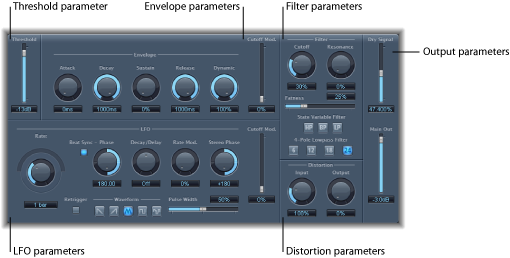
- Threshold parameter: Sets an input level that—if exceeded—triggers the envelope or LFO, which are used to dynamically modulate the filter cutoff frequency. See AutoFilter Threshold Parameter.
- Envelope parameters: Define how the filter cutoff frequency is modulated over time. See AutoFilter Envelope Parameters.
- LFO parameters: Define how the filter cutoff frequency is modulated by the LFO. See AutoFilter LFO Parameters.
- Filter parameters: Control the tonal color of the filtered sound. See AutoFilter Filter Parameters.
- Distortion parameters: Distort the signal both before and after the filter. See AutoFilter Distortion Parameters.
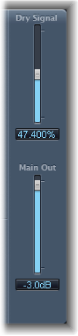
- Output parameters: Set the level of both the dry and effect signal. See AutoFilter Output Parameters.
AutoFilter Threshold Parameter
The Threshold parameter analyzes the level of the input signal. If the input signal level exceeds the set threshold level, the envelope and LFO are retriggered—this applies only if the Retrigger button is active.
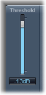
The envelope and LFO can be used to modulate the filter cutoff frequency.
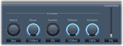
AutoFilter Envelope Parameters
The envelope is used to shape the filter cutoff over time. When the input signal exceeds the set threshold level, the envelope is triggered.
AutoFilter LFO Parameters
The LFO is used as a modulation source for filter cutoff.

- Coarse Rate knob, Fine Rate slider and field: Used to set the speed of LFO modulation. Drag the Coarse Rate knob to set the LFO frequency in Hertz. Drag the Fine Rate slider (the semicircular slider above the Coarse Rate knob) to fine-tune the frequency.
Note: The labels shown for the Rate knob, slider, and field change when you activate Beat Sync. Only the Rate knob (and field) is available.
AutoFilter Filter Parameters
The Filter parameters allow you to precisely tailor the tonal color.
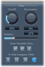
- Cutoff knob and field: Sets the cutoff frequency for the filter. Higher frequencies are attenuated, whereas lower frequencies are allowed to pass through in a lowpass filter. The reverse is true in a highpass filter. When the State Variable Filter is set to bandpass (BP) mode, the filter cutoff determines the center frequency of the frequency band that is allowed to pass.
- Fatness slider and field: Boosts the level of low frequency content. When you set Fatness to its maximum value, adjusting Resonance has no effect on frequencies below the cutoff frequency. This parameter is used to compensate for a weak or “brittle” sound caused by high resonance values, when in the lowpass filter mode.
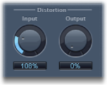
AutoFilter Distortion Parameters
The Distortion parameters can be used to overdrive the filter input or filter output. The distortion input and output modules are identical, but their respective positions in the signal chain—before and after the filter, respectively—result in remarkably different sounds.