The Phaser effect combines the original signal with a copy that is slightly out of phase with the original. This means that the amplitudes of the two signals reach their highest and lowest points at slightly different times. The timing differences between the two signals are modulated by two independent LFOs. In addition, the Phaser includes a filter circuit and a built-in envelope follower that tracks volume changes in the input signal, generating a dynamic control signal. This control signal alters the sweep range.
Sonically, phasing is used to create whooshing, sweeping sounds that wander through the frequency spectrum. It is a commonly used guitar effect, but it is suitable for a range of signals.
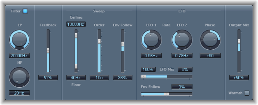
Phaser parameters
Filter button: Turn the filter section on or off.
LP and HP knobs and fields: Set the cutoff frequency of the lowpass (LP) and highpass (HP) filters.
Feedback slider and field: Determine the amount of effect signal routed back to the input.
Ceiling/Floor sliders and fields: Determine the frequency range affected by the LFO modulations. Drag the blue area to move the entire range.
Order slider and field: Choose phaser algorithms. The more orders, the stronger the effect.
The 4, 6, 8, 10, and 12 settings switch between five different phaser algorithms. All are modeled on analog circuits, with each designed for a specific application.
The odd-numbered settings (5, 7, 9, and 11) don’t generate actual phasing effects. The more subtle comb filtering effects produced by odd-numbered settings can, however, be useful.
Env Follow slider and field: Determine the impact of incoming signal levels on the frequency range (set with the Ceiling and Floor controls).
LFO 1/2 Rate knobs and fields: Set the speed for each LFO.
LFO Mix slider and fields: Determine the ratio between the two LFOs.
Env Follow slider and field: Determine the impact of incoming signal levels on the speed of LFO 1.
Phase knob and field: Control the phase relationship between the individual channel modulations. Available only in stereo instances. At 0°, the extreme values of the modulation are achieved simultaneously for both channels. At 180° or −180°, there is the greatest possible distance between the modulation phases of both channels.
Output Mix slider and field: Determine the balance of dry and wet signals. Negative values result in a phase-inverted mix of the effect and direct (dry) signal.
Warmth button: Click to turn on a distortion circuit, which is suitable for warm overdrive effects.