Modulation Delay is based on the same principles as the Flanger and Chorus effects, but you can set the delay time, allowing both chorus and flanging effects to be generated. It can also be used without modulation to create resonator or doubling effects. The modulation section consists of two LFOs with variable frequencies.
Although rich, combined flanging and chorus effects are possible, the Modulation Delay is capable of producing some extreme modulation effects. These include emulations of tape speed fluctuations and metallic, robot-like modulations of incoming signals.
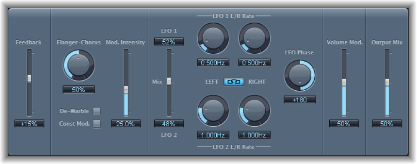
Modulation Delay parameters
Feedback slider and field: Set the amount of effect signal routed back to the input. Use a high Feedback value for strong modulations. If you want to double the signal, don’t use Feedback. Negative values invert the phase of the feedback signal, resulting in more chaotic effects.
Flanger-Chorus knob and field: Set the basic delay time. Set to the far left position to create flanger effects, to the center for chorus effects, and to the far right to hear clearly discernible delays.
De-Warble button: Click to make sure the pitch of the modulated signal remains constant.
Constant Modulation button: Click to make sure the modulation width remains constant, regardless of the modulation rate.
Note: When Const Mod is enabled, higher modulation frequencies reduce the modulation width.
Modulation Intensity slider and field: Set the modulation amount.
LFO Mix slider and fields: Determine the balance between the two LFOs.
LFO 1/2 Rate knobs and fields: Set the modulation rate for the left and right stereo channels.
Note: The right LFO Rate knob is available only in stereo instances, and it can be set separately only if the Left Right Link button is not enabled.
LFO Left Right Link button: Link the modulation rates of the left and right stereo channels. Adjustment of either Rate knob affects the other channel.
LFO Phase knob and field: Control the phase relationship between individual channel modulations. Available only in stereo instances.
At 0°, the extreme values of the modulation are achieved simultaneously for both channels.
At 180° or −180°, you achieve the greatest possible distance between the modulation phases of both channels.
Note: The LFO Phase parameter is available only if the LFO Left Right Link button is active.
Volume Mod slider and field: Determine the impact of LFO modulation on the amplitude of the effect signal.
Output Mix slider and field: Determine the balance between dry and wet signals.
All Pass button (Extended Parameters area): Click to introduce an additional allpass filter into the signal path. This filter shifts the phase angle of a signal, influencing its stereo image.
All Pass Left and All Pass Right sliders and fields (Extended Parameters area): Determine the frequency at which the phase shift crosses 90°—the halfway point of the total 180°—for each of the stereo channels.