Controlling Signal Flow in the Mixer
You can control signal flow in the Mixer using aux channel strips, output channel strips, or multi-output instruments.
You use aux channel strips to create subgroups or to route a signal to multiple destinations. You use output channel strips for subgrouping purposes. You use multi-output instruments to individually process sounds and outputs.
Creating Aux Channel Strips in the Mixer
Aux channel strips can be used as send returns, as subgroups, to route a signal to multiple destinations, and as additional destination channels for multi-output instruments.
Typically, you create aux channel strips as you need them. There are three ways to do this:
An aux channel strip is created automatically when a send assignment is made from a channel strip, except when the chosen bus is already in use as an input source on another channel strip.
When a multi-output instrument such as the EXS24 mkII is inserted into an instrument channel strip, several aux channel strip assignments are made “behind the scenes.” You then must create the required number of aux channel strips by clicking the Add (+) button at the bottom of the instrument channel strip. Each time you click it, a new aux channel strip is created (and automatically assigned to particular instrument outputs).
The third way to create aux channel strips is by clicking the Add (+) button at the left side of the Mixer, or by choosing Options > Create New Auxiliary Channel Strips. Both methods open the following dialog:
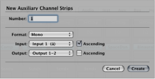
Enter a number, then choose settings from the Format, Input, and Output pop-up menus, and click Create.
Using Aux Channel Strips in the Mixer
You use aux channel strips to create subgroups, for submixing purposes. You also use them to route a signal to multiple output destinations.
For details about how to create aux channel strips, see Creating Aux Channel Strips in the Mixer.
Creating Mix Subgroups
You can group several channel strips and route them via a single bus to a single aux channel strip. This provides you with one set of controls over the entire group.
For example, your mix contains multiple drum tracks that you want to manage using a single set of channel strip controls; or you want to put a compressor across the whole drum kit. You can do this by sending each of the drum tracks to the same bus, which in turn sends their signals to the same aux channel strip. You might then route your vocal tracks to a second aux channel strip, providing a separate group control for these channel strips. Finally, you have the option to output both subgroups (drums and vocals) to the same destination or to separate destinations.
There is no restriction on the number of channel strips you can send to a subgroup.
Note: There are some similarities between using aux channel strips as subgroups and working with Mixer groups (see Working with Mixer Groups). You can control the group/subgroup properties from one set of channel strip controls. However, Mixer groups are used to control channel strip group properties, and not the signal flow.
Select multiple channel strips by doing one of the following:
Shift-click the required channel strips.
Drag over the background of the required channel strips (drag horizontally across multiple channel strips over the word Inserts, or I/O text, for example).
Point to the Output slot of any selected channel strip, hold down the mouse button, and choose the required Bus (Bus 1, for example).
The Output slots of all selected channel strips change to Bus 1.
A new aux channel strip is created, except when the chosen bus is already in use as an input source on another channel strip. Its Input slot contains the channel strip signal flow coming via Bus 1.
Open the Output slot of the aux channel strip to choose the output destination for the main mix.
Use the aux channel strip controls to process the submix—adding inserts, setting level and pan, and so on.
Sending Signals to Multiple Destinations
You can route a signal to several output destinations, using aux channel strips.
For example, you might have a main signal with the output destination set to external speakers. At the same time, you would like to hear the signal as a separate headphone mix, including some additional effects. To do this, you would set up two separate output destinations for your signal, with the aux channel strips controlling the headphone mix, including the additional effects.
Open the channel strip’s Output slot, then select the main output destination for the mix—such as speakers.
Open the channel strip’s Send slot, then select the bus to send the separate signal to.
An aux channel strip is created automatically. Your chosen bus is reflected in the aux channel strip’s Input slot.
Open the aux channel strip’s Output slot, then select the second output destination for the mix—such as headphones.
Your signal flow is now routed to two separate output destinations. The main signal flow to the speakers is heard in its “dry” state. The second signal flow—via a bus to the aux channel strip, and output to headphones—can be modified and heard in its “wet” state.
Using Multi-Output Instruments in the Mixer
There are two reasons to use multi-output instruments in your mix: to individually process each sound in a drum kit, for example, with different effects; to route the different virtual instrument outputs to different outputs on your audio interface. All of this is done using the aux channel strip.
Logic Pro supports the multiple outputs of the EXS24 mkII, Ultrabeat, and all Audio Unit instruments. One or more multi-output options may be displayed in addition to the mono and stereo versions shown in the instrument plug-in menu.
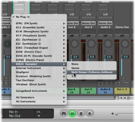
The plug-in menu offers additional information about an output configuration, such as:
Instrument Name: Multi Output (2 x stereo, 4 x mono)
Instrument Name: Multi Output (4 x stereo)
Note: Not all instruments (Logic Pro or software from another company) are multi-output capable. If the instrument does not provide a multi-output option, it is not equipped with multiple output facilities.
Choose the multi-output instance in the plug-in menu.
The first two outputs of a multi-output instrument are always played back as a stereo pair by the instrument channel strip that the plug-in is inserted into.
Additional outputs (3 and 4, 5 and 6, and so on) are accessed via aux channel strips.
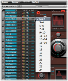
Within the instrument interface, you need to set up the output routing for individual sounds or samples. This is generally done using a menu with entries such as Main, 34, 56, and so on.
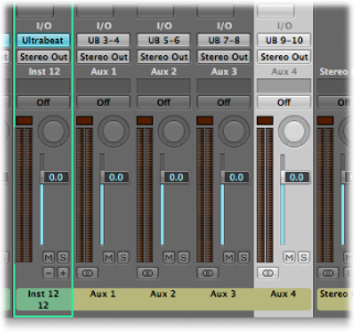
In the Mixer, click the Add (+) button of the instrument channel strip that you have inserted the multi-output instrument in—such as Ultrabeat.
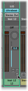
Note: The Add button (+) appears only on multi-output instrument channel strips.
An aux channel strip appears to the right of the instrument channel strip, already assigned to the inserted multi-output instrument.
Repeatedly click the Add button (+) to create more aux channel strips, for all stereo or mono outputs available to the instrument plug-in.
You should create only as many aux channel strips as required for the number of outputs used by the multi-output instrument.
Following the creation of the first aux channel strip for your multi-output instrument, a Delete button (–) appears beside the Add button (+).
Click the Delete button (–) to remove aux channel strips.
Using Output Channel Strips in the Mixer
You use output channel strips to assign submixes to physical hardware outputs of your interface. You do this by routing multiple channel strips to a common output path via their Output slots.
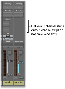
When using output channel strips in this way, you cannot apply any further send effects to the signal flow, as you would using aux channel strips. You can, however, control settings and insert effect plug-ins using the individual controls of the output channel strip.
In some cases you might want to prevent individual output channel strips from being controlled by the master channel strip—outputs used as send effects to external hardware devices, for example. Simply switch such output channel strips to Solo-Safe mode by Control-clicking their Solo button and they won’t be affected by the master channel strip. See Soloing Channel Strips.
The Insert slots of output channel strips allow signal processing during the mastering process, as well as during normal playback. Typical mastering tools are the compressors, deessers, and equalizers. Due to technical reasons, you can only use plug-ins that don’t require mono to stereo conversions. In other words, you can use stereo to stereo plug-ins on stereo output channel strips, and mono to mono plug-ins on mono output channel strips. Surround (or multi-mono) versions of plug-ins can be used on mono or stereo output channel strips. Mono to multi-mono variants can be used on mono output channel strips. Stereo to surround, stereo to multi-mono, and true surround versions of plug-ins are accessible in stereo output channel strips.
Defining a Channel Strip’s Stereo Output
In Logic Pro you can choose the physical output pair on which the stereo output is played. By default, it is played on Stereo Output (Output 1-2). But what if you are exchanging projects with another studio that uses a different output pair when stereo monitoring, for example? You can simply change the stereo output preference.
Open Audio preferences by doing one of the following:
Choose Logic Pro > Preferences > Audio (or use the Open Audio Preferences key command).
Click the Preferences button in the Arrange toolbar, then choose Audio from the pop-up menu.
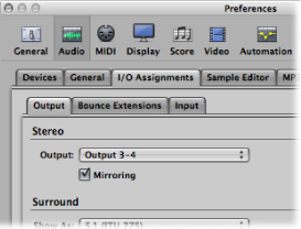
Click the I/O Assignments tab, then the Output tab.
Choose an output pair from the Output pop-up menu in the Stereo section.
The Mirroring checkbox becomes available for all chosen output pairs, with the exception of Output 1-2.
Do one of the following:
Deselect the Mirroring checkbox to have the output signal routed to the chosen output pair (Output 3-4, for example).
Select the Mirroring checkbox to have the output signal routed to the chosen output pair (Output 3-4, for example), as well as to the physical outputs (Output 1-2). This is useful when feeding the signal to a second pair of monitors, for example.
You can also define the output pair for individual channel strips in the Mixer.
Open the Output slot of a channel strip, and choose an output pair from the Output pop-up menu.