Creating Control Surface Groups
If you have multiple control surface units in your system, you can define how they relate to each other, and create control surface groups. A control surface group consists of multiple devices that you combine to create a single, unified virtual control surface.
You can create up to 20 control surface groups. Each group can consist of any number of physical devices. The only limiting factor is the number of available MIDI In and Out ports (or USB/FireWire “MIDI” ports, if you are using a USB or FireWire control surface).
You can independently determine the default behavior of each device in a group. For more information, see the Device Parameters section.
Choose Logic Pro > Preferences > Control Surfaces > Setup to open the Control Surfaces Setup window.
In the Setup window, drag the icons of the control surfaces you want to group, so that they form a single horizontal row.
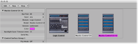
The order of the icons from left to right defines the order in which tracks and parameters are arranged and displayed on the devices.
Choose Logic Pro > Preferences > Control Surfaces > Setup to open the Control Surfaces Setup window.
In the Setup window, arrange the icons for the control surfaces in separate rows—that is, one above the other.
Pictured below is a multiple group example with two Mackie Controls, three Mackie Control XTs, and one HUI:
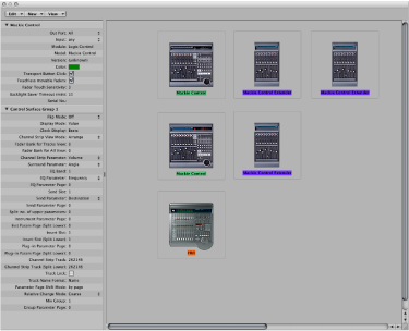
The top row, consisting of the Mackie Control #1, Mackie Control XT #1, and Mackie Control XT #2, forms a single control surface group with 24 channels. Mackie Control #1 controls channels 1 to 8, XT #1 controls channels 9 to 16, and XT #2 handles channels 17 to 24.
In the second row, the Mackie Control #2 and Mackie Control XT #3 form a second control surface group, controlling instruments (on channels 1 to 8) and auxes (on channels 9 to 16).
In the third row, the HUI forms a single unit control surface group.
Each group has individual settings, such as Flip mode, Display mode, Plug-in Parameter Bank Offset, and others. This allows you to access, edit, and automate different sections of the Logic Pro Mixer.
In the example above, the three units in the top row could be used to control audio and MIDI channel strips. In the second row, Mackie Control #2 could be used to control instrument channel strips 1 to 8, and XT #3 could be used to control aux channel strips 1 to 8. The HUI could be used to edit group definitions. The physical placement of units, and the way you use them, is completely flexible.
Note: In most situations, the placement of your control surface units in relation to each other should be the same onscreen as in the real world. Simply position the icons in your control surface group accordingly.
Once you have created a control surface group, you can configure it in the Setup window. For more information, see Control Surface Group Parameters.