Working with Channel Strips in Edit Mode
Channel strips are the building blocks of your patches. They contain the instruments and effects for the sounds you use in performance. MainStage channel strips use the channel strip interface familiar from Logic Pro, with the same structure and many of the same functions as Logic Pro channel strips. The main features of MainStage channel strips are shown below:
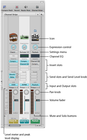
- Icon: Shows the type of channel strip for easy identification.
- Expression control: Allows you to quickly adjust the expression value of the channel strip.
- Settings menu: Allows you to load and save the entire routing configuration of a single channel strip, including all loaded plug-ins and settings.
- Channel EQ: Allows you to add an EQ effect to sculpt the sound of the channel strip signal before applying other effects.
- Insert slots: Allow you to insert up to 15 effect plug-ins into each audio, instrument, aux, and output channel strip.
- Send slots: Allows you to route a channel strip’s signal to an aux channel strip. Sends are commonly used to apply the same effect or effects to several signals.
- Send level knob: Controls the amount of signal sent to an aux channel strip. This knob appears when a Send slot is activated.
- Input slot: Sets the channel strip’s input source. Depending on the channel strip type, it can be a physical input, a bus, or a software instrument plug-in—in this case it is known as an Instrument slot.
- Output slot: Sets the channel strip’s output path. It can be a physical output or a bus.
- Pan knob: On a mono channel strip, the Pan/Balance knob controls the position of the signal in the stereo image. On a stereo channel strip, it controls the relative level of the left and right signals at their outputs.
- Volume fader: Sets a channel strip’s playback volume.
- Mute button: Mutes and unmutes the channel strip.
- Solo button: Solos and unsolos the channel strip.
- Level meter: Displays a channel strip’s playback level.
- Peak level display: Updates during playback to show the highest peak level reached.
In MainStage, you can use audio, software instrument, and auxiliary (aux) channel strips in your patches and sets, and also at the concert level. You can also use external instrument patches to “play” external hardware devices and ReWire applications. You can use channel strips in MainStage just as you can in Logic Pro. You can adjust the volume level using the Volume fader, adjust the pan position using the Pan knob, and mute or solo the channel strip using the Mute and Solo buttons.
A MainStage concert can have a maximum of 1023 software instrument channel strips, 512 audio channel strips, 256 external instrument channel strips, and 256 auxiliary (aux) channel strips.
You can add effects using the Insert slots, send the signal to an auxiliary channel (aux) using the Sends slots, and choose a different output from the Output slot. For audio channel strips, you can change the format between mono and stereo using the Format button. For software instrument channel strips, you can change the instrument using the Instrument slot. You can also choose, copy, and save channel strip settings, choose a different channel strip type, or reset the channel strip from the Settings menu.
If you are famliar with channel strips from Logic Pro, note that there are a few differences between MainStage channel strips and Logic Pro channel strips:
MainStage channel strips include an Expression dial so that you can easily see the current MIDI Expression being received by the channel strip.
MainStage channel strips do not have a Record Enable or Bounce button.
MainStage audio channel strips can use automatic Feedback Protection to alert you when feedback occurs on the channel. For information about using Feedback Protection, see Using Feedback Protection with Channel Strips.
MainStage audio channel strips do not have an input monitoring (i) button. You can use the Mute button to silence the channel strip.
In MainStage, you can use the Format button to select mono or stereo format. MainStage does not support surround input or surround processing.
MainStage channel strips do not have Group or Automation Mode pop-up menus.
MainStage channel strips include a Change All option in both Input and Output pop-up menus that you can use to change either the input or output for all channel strips in a patch, a set, or for the overall concert.
In MainStage, the selected channel strip is highlighted in white.
Only one channel strip in each patch–the first audio channel strip–sends audio to the Tuner. The channel strip that sends audio to the Tuner is indicated by a tuning fork icon at the top of the channel strip.
In MainStage, the name of the channel strip changes when you select a new channel strip setting, unless you have renamed it.
In MainStage, the channel strip number (at the bottom of the channel strip) reflects its order in the patch, not the concert.
Surround plug-ins are not available in MainStage.
You can choose the information displayed on the channel strip, including latency information, by Control-clicking the channel strip and choosing the information you want to display from the shortcut menu.
The Playback plug-in is available only in MainStage, not in Logic Pro.
The Loopback plug-in is available only in MainStage, not in Logic Pro.
For complete information about the instruments and effects available in Logic Pro, see the Logic Pro Instruments and Logic Pro Effects manuals. To learn how to add a channel strip, see Adding a Channel Strip. To learn how to change a channel strip setting, see Changing a Channel Strip Setting.
Selecting Channel Strips
When you add a channel strip to a patch (or add a channel strip at the set or concert level), the channel strip is selected in the Channel Strips area, and available settings appear in the Channel Strip Settings browser. You can select a channel strip directly by clicking it in the Channel Strips area and also select an adjacent channel strip by using key commands:
Key command | Selection |
|---|---|
Left Arrow | The channel strip to the left |
Right Arrow | The channel strip to the right |
Showing Signal Flow Channel Strips
In addition to the channel strips in a patch, you can view and edit signal flow channel strips in the Channel Strips area. Signal flow channel strips include the Output and Master channel strips for the concert, auxes that are receiving signal from a channel strip in the patch, and any set- or concert-level channel strips that are available when the patch is selected. You can also view signal flow channel strips at the set level.
When you show signal flow channel strips, channel strips at the concert level, including Output and Aux channel strips, include a small concert icon near the top of the channel strip to make it easy to distinguish them from patch-level channel strips. Channel strips at the set level include a small folder icon so they can also be easily distinguished.
You can edit signal flow channel strips in the Channel Strips area. For example, you can adjust the volume fader or pan slider of a signal flow channel strip, or add effects to an aux channel strip.
Choose Show Signal Flow Channel Strips from the Action menu in the upper-right corner of the Channel Strips area.
Creating an Alias of a Channel Strip
You can create an alias of a channel strip and use the alias in different patches or sets. Aliases allow you to share highly memory-intensive plug-ins, such as third-party multichannel instruments and samplers, between different patches, rather than creating multiple instances of these plug-ins. In some cases, creating an alias can be more efficient (use fewer resources) than adding a concert- or set-level channel strip.
In the Channel Strips area, select the channel strip.
Choose Edit > Copy, or press Command-C (default).
In the Patch List, select the patch in which you want to use the alias.
Choose Edit > Paste as Alias, or press Command-Option-V (default).
The alias is pasted after the last channel strip in the patch (but before any signal flow channel strips, if they are visible). An alias icon appears near the top of the alias to distinguish it from the channel strips in the patch.
You can use an alias in multiple patches or sets. When you change settings on the original channel strip (with the exception of volume, pan, and expression), those changes are reflected in the aliases of the channel strip. You may want to audition each patch that uses an alias after changing the settings of the original channel strip, to make sure it sounds the way you want.
Note: You can’t import a patch or set containing an alias, because the aliased channel strip may not be available.
You can create an alias of a multi-output instrument, such as the EXS24 mkII, to use in another patch or set in the concert. When you copy a multi-output instrument to create an alias, be sure to select all of the aux channel strips for the instrument so that the complete multi-output instrument is pasted as an alias. For information about using multi-output instruments in MainStage, see Using Multiple Instrument Outputs in MainStage.
Editing Channel Strips in MainStage
You can add instruments to software instrument channel strips and add effects to any channel strip in the Channel Strips area. Adding instruments and effects to a channel strip is the same in MainStage as it is in Logic Pro.
You edit channel strip parameters in the Channel Strip Inspector, which appears below the workspace when the channel strip is selected in the Channel Strips area. You can set the key range and velocity offset, create a controller transform, and filter MIDI control messages to the channel strip. You can also rename the channel strip and change the channel strip color and icon. The Channel Strip Inspector has four tabs, which provide the following functions:
- Channel Strip Library and Plug-In Library: With a channel strip selected, you can choose channel strip settings from the Channel Strip Library. With an Insert slot selected, you can choose settings for the plug-in from the Plug-in Library.
- Attributes: You can rename the channel strip and choose a different channel strip color and icon.
- MIDI Input: You can create controller transforms in the MIDI Input tab. For software instrument and external instrument channel strips, you can also choose the MIDI input device, filter MIDI input, transpose the instrument, and create velocity scaling graphs.
- Layer Editor: For software instrument and external instrument channel strips, you can define the key range, set floating split points, and set the minimum and maximum velocity for the channel strip.
Using the Channel Strip Library you can access any available channel strip. Some channel strips, however, include plug-ins (particularly Space Designer) not suited for live performance because of their intensive CPU usage. Using these channel strips can affect the performance of your concert, resulting in audio dropouts and other issues.
Logic Pro surround effect plug-ins cannot be used with MainStage. If you choose a channel strip setting containing one of these effects, the unused effects are shown disabled (gray, with a diagonal line running through the effect name).
Choosing Channel Strip Settings
You can quickly change the instrument, effects, and other parameters for a channel strip by choosing a new channel strip setting. You can choose a new channel strip setting in one of two ways: by using the Channel Strip Library or by using the Settings button at the top of the channel strip.
In the Channel Strips area, select the channel strip you want to change.
The selected channel strip is highlighted with a blue outline.
In the Channel Strip Inspector, click the Channel Strip Library tab.
Available settings for the channel strip appear in the Channel Strip Library. MainStage built-in channel strip settings appear in a series of folders with different instrument categories. If you have GarageBand installed, or have one or more Jam Packs installed on your computer, those settings appear below the built-in settings.
Click a category from the column on the left, then click subcategories from the columns on the right until you see the settings you want.
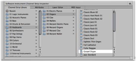
You can select a recent channel strip setting by clicking Recent in the column on the left, and then selecting a recent setting from the second column. You can also choose a new channel strip setting from the Settings menu at the top of the channel strip.
Click the Settings button at the top of the channel strip, then choose a new setting from the menu that appears.
When you choose new channel strip settings from the Settings menu, the selected channel strip setting does not appear selected in the Channel Strip Library.
You can also search for channel strip settings by name.
In the Channel Strip Inspector, select the Channel Strip Library tab.
Choose Find in Library from the Action menu in the upper-right corner of the Channel Strip Inspector.
In the dialog that appears, type the text you want to search for.
The channel strip with the text in its name appears selected in the library.
If more than one channel strip includes the search text, choose “Find Next in Library” from the Action menu to cycle through the channel strips with names containing the text.
To change the channel strip setting, click the name of the new setting in the Channel Strip Inspector.
The Channel Strip Library shows all available channel strip settings, including settings that may not be useful in MainStage. If you choose a channel strip setting containing plug-ins not usable in MainStage, the plug-ins appear with a bold diagonal line in the Channel Strips area.
Renaming a Channel Strip
When you add a channel strip to a patch, the channel strip has a default name. You can rename channel strips to distinguish your custom settings from the default ones.
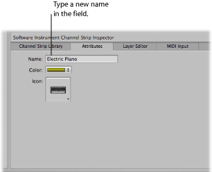
In the Attributes tab of the Channel Strip Inspector, select the name in the Name field and type a new name.
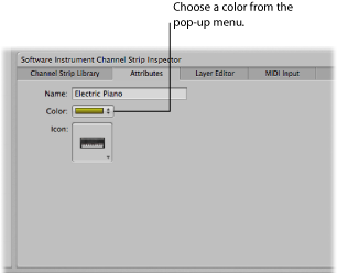
Changing the Channel Strip Color
Each channel strip has a color, which appears at the bottom of the channel strip and as a layer above the keyboard screen control in the workspace and the Layer Editor. You can change the color of a channel strip to make it easier to visually distinguish channel strips.
In the Attributes tab of the Channel Strip Inspector, choose a color from the Color pop-up menu.
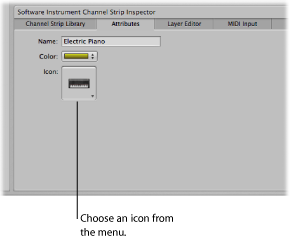
Changing the Channel Strip Icon
When you add a channel strip, the channel strip has a default icon, which appears above the Settings menu. You can change the icon to help visually distinguish channel strips with different instrument types or uses.
In the Attributes tab of the Channel Strip Inspector, choose an icon from the Icon well.
Using Feedback Protection with Channel Strips
You can use Feedback Protection on audio and external instrument channel strips in MainStage. Feedback Protection is turned on by default for audio channels strips and off by default for external instrument channel strips. You can turn Feedback Protection on or off for individual channel strips in the Channel Strip Inspector.
In the Attributes tab of the Channel Strip Inspector, select the Feedback Protection checkbox to turn Feedback Protection on. Deselect the checkbox to turn it off.
When Feedback Protection is turned on for a channel strip, MainStage alerts you when it detects feedback on the channel. When the feedback alert appears, the channel is temporarily silenced. You can then choose to mute the channel while you find and eliminate the source of the feedback, disable Feedback Protection for all audio and external channel strips in all concerts, or continue to use the channel and receive alerts when feedback occurs.
For more information about disabling Feedback Protection globally, see Audio Preferences.
Setting Keyboard Input for a Software Instrument Channel Strip
In the Channel Strip Inspector, you can choose the keyboard controller from which the channel strip receives MIDI input. If you are using a multitimbral instrument, you can also choose the input for each MIDI channel. For example, you can use the EVB3 instrument as a multitimbral instrument, and send input to the upper and lower register and the foot pedal using three separate MIDI channels.
In the Channel Strip Inspector, click the MIDI Input tab.
Choose the MIDI input device from the Keyboard pop-up menu in the Input section.
The names in the Keyboard pop-up menu correspond to keyboard screen controls in the workspace.
In the Channel Strip Inspector, click the MIDI Input tab.
Choose Multitimbral from the Keyboard pop-up menu in the Input section.
In the Multitimbral Settings dialog, choose the input device for each MIDI channel you want to receive MIDI input.
Transposing Software Instrument Channel Strips
You can transpose (change the pitch of) a software instrument channel strip. When you transpose a channel strip, every MIDI note received by the channel strip is transposed by the number of semitones set in the Transpose value slider.
Select the channel strip in the Channel Strips area.
In the MIDI Input tab of the Channel Strip Inspector, set the value using the Transpose value slider. You can click the value and drag up or down to set the value, click the up arrow or down arrow, or double-click the value and type a new value.
Filtering MIDI Messages
You can filter some MIDI messages for a channel strip in the Channel Strip Inspector. When you select one or more MIDI message types in the Filter section of the Channel Strip Inspector, the corresponding MIDI message types are filtered out of any incoming MIDI data and are not sent to the channel strip.
You can filter the following types of MIDI messages:
Pitch Bend
Sustain (control message 64)
Modulation (control message 1)
Expression (control message 11)
Aftertouch
In the Channel Strip Inspector, click the MIDI Input tab.
In the Filter section of the MIDI Input tab, select the checkbox for the MIDI messages you want to filter.
If you have created a controller transform, you can filter the input message type, and the controller transform will still send its output message type. It is also possible to filter the output message type, but in this case the output of the controller transform will be filtered.
Setting a Channel Strip to Ignore Hermode Tuning
If a patch (or the concert or set containing the patch) is set to use Hermode tuning, but the patch contains a channel strip (for example, one with a drum or percussion instrument) that you do not want to use Hermode tuning, you can set the individual channel strip to ignore Hermode tuning.
In the MIDI Input tab of the Channel Strip Inspector, select the Ignore Hermode Tuning checkbox.
For information about using Hermode tuning, see the Logic Pro User Manual.
Working with Graphs
Using graphs, you can graphically remap the values for some MIDI control messages so that input values from your controller produce different output values for the channel strip or plug-in parameter. Graphs make it easier to see and modify a range of values for a parameter, such as velocity or filter cutoff.
You can use graphs for the following types of parameters:
Controller transforms
Velocity scaling (both input velocity and note input)
Parameters to which a screen control is mapped
You open a graph window by clicking the button for that type of graph in the appropriate Inspector. The Transform and Velocity Scaling graphs for the selected channel strip are available in the MIDI Input tab of the Channel Strip Inspector. The Parameter graph for the selected screen control is available in the tab for the individual mapping as well as in the Mappings tab in the (Edit mode) Screen Control Inspector.
The graph shows the range of input values on the horizontal (x) axis, moving from left to right, and shows the range of output values on the vertical (y) axis, moving from bottom to top.
In the graph window, you have several ways of working. You can edit the graph curve directly, edit values numerically using the Precision Editor, or use the Curve buttons to set the graph to one of the predefined curves.
Most of the ways you edit graphs are the same, regardless of the type of graph—although there are a few features specific to one or another type. For Parameter graphs, you can change the minimum and maximum range values for the graph using the Range Min and Range Max value sliders. For information about controller transforms, see Creating Controller Transforms. For information about velocity scaling, see Scaling Channel Strip Velocity. For information about parameter mapping graphs, see Using Parameter Mapping Graphs.
Select the channel strip or screen control you want the graph to apply to.
Select the MIDI Input tab (for transform and velocity scaling graphs) or the Mapping tab (for parameter mapping graphs).
Click the graph button for the type of graph you want to edit.
The graph window opens.
Do one of the following:
Click one of the Curve buttons to set the graph to one of the preset curves.
Click the curve at the point where you want to add a node, then drag the node to the desired value. Drag horizontally to change the input value, or vertically to change the output value.
As you drag, the current values of the node appear next to the pointer.
Double-click the curve at the point where you want to add a node, then edit the values for the node in the Precision Editor.
Option-click any part of the curve (except a node), then drag the dotted part of the curve to make the curve nonlinear.
Continue adding and adjusting points on the curve until you achieve the result you want.
When you are finished, click the close button at the upper-left corner of the graph window to close it.
In the graph window, click the Invert button.
In the tab for the mapping, select the Invert Parameter Range checkbox.
Click the Revert to Default button at the top of the graph window.
After you have edited a graph, the button for the graph in the Inspector shows the edited shape of the graph in a dark blue color to make it easier to identify which graphs you have edited and how.
Press Escape (Esc).
Creating Controller Transforms
Using a transform graph, you can remap the values for some MIDI control messages so that input values from your controller produce different output values for the channel strip. A common use of the transform is for expression scaling, where input MIDI expression values are mapped to different output values on a graphic curve.
In addition, you can transform input values for one message type to output values for another message type. For example, you can transform MIDI volume values from your controller to send expression values to the channel strip, or transform input breath values to send modulation values. The transform graph provides a very flexible way of remapping both the values and the output destination for these MIDI control messages. In MainStage, you can transform values for expression, modulation, MIDI volume, and breath control messages.
You choose the input and output message types and graphically create transform curves in the MIDI Input tab of the Channel Strip Inspector. In a transform graph, the horizontal axis represents input values from your controller, and the vertical axis represents output values sent to the channel strip.
In the Channel Strips area, select the channel strip for which you want to create a controller transform.
In the Channel Strip Inspector, select the MIDI Input tab.
In the Controllers section, choose the input message type from the Input pop-up menu.
Choose the output message type from the Output pop-up menu.
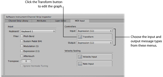
In the MIDI Input tab of the Channel Strip Inspector, click the Transform button.
The Transform graph opens.
If a patch contains more than one channel strip with a transform graph, the transform curves for the other channel strips in the patch appear in the controller Transform graph window behind the current curve. Each channel strip in the patch can have its own controller transform.
For information about editing the graph, see Working with Graphs.
Scaling Channel Strip Velocity
You can scale the output velocity of a channel strip using the Velocity Scaling graphs. You can scale output velocity based on note input or input velocity.
When you perform velocity scaling, each input velocity (regardless of the note being played) is scaled to the output velocity.
When you perform note scaling, output velocity is scaled depending on the note in the key range. This is useful when you want to have a parameter change in different parts of the key range; for example, when a filter or attack parameter opens for higher note values to give a brighter, sharper sound.
In the Channel Strips area, select the channel strip on which you want to perform velocity scaling.
In the Channel Strip Inspector, select the MIDI Input tab.
In the MIDI Input tab, do one of the following:
To open the velocity input graph, select the Velocity Input button.
To open the note input graph, select the Note Input button.
The selected velocity scaling graph opens.
For information about editing the graph, see Working with Graphs.
Creating Keyboard Layers and Splits
If you play a keyboard controller, you can easily create keyboard layers and splits in your MainStage patches. You create layers and splits by adding two or more channel strips to a patch and setting the Low Key and High Key for each channel strip to define its key range. The key range defines the range of notes on a keyboard controller that trigger sound from a software instrument or external instrument in the channel strip. You can define key ranges so that they overlap (for layered sounds) or are contiguous (for splits).
The Layer Editor tab in the Channel Strip Inspector shows the key range for each channel strip in a patch and in the concert or set containing the patch (if either includes a channel strip with a key range). You can define the key range for a channel strip in one of several ways: you can drag the edges of the layer, use the Learn buttons to define the Low and High keys, or use the Low Key and High Key value sliders.
In the Channel Strip Inspector, click the Layer Editor tab.
In the Layer Editor, move the pointer over the left edge of the layer you want to change/define.
The pointer changes to a resize pointer.
Drag the left edge of the layer to the note you want to use as the low key (the lowest note in the key range).
Move the pointer over the right edge of the layer.
Drag the right edge of the layer to the note you want to use as the high key (the highest note in the key range).
In the Channel Strips area, select the channel strip.
In the Channel Strip Inspector, click the Layer Editor tab.
Click the Learn button next to the Low Key value slider.
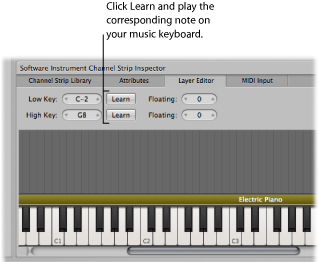
On your keyboard controller, press the key you want to set as the lowest key in the key range.
Click the Learn button again to turn off Learn mode for the Low Key.
Click the Learn button next to the High Key value slider.
On your keyboard controller, press the key you want to set as the highest key in the key range.
Click the Learn button again to turn off Learn mode for the High Key.
When you play the patch, you hear the channel strip when you play notes inside the key range. When you play notes outside the key range, no sound is generated from the channel strip.
In the Channel Strips area, select the channel strip.
In the Channel Strip Inspector, click the Layer Editor tab.
Change the value in the Low Key value slider.
You can click the value and drag vertically, click the up arrow or down arrow, or double-click the value and type a new value.
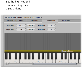
Change the value in the High Key value slider.
You can click the value and drag vertically, click the up arrow or down arrow, or double-click the value and type a new value.
Setting Floating Split Points
When a key range has a floating split point, the notes that define the boundaries of the key range ends change depending on the keys you play as you approach the boundary of the key range. You set floating split points in the Layer Editor tab of the Channel Strip Inspector.
Floating split points can be explained using an example. If you set the Low Key of a key range to C1, set a floating split point value of 3, then play notes immediately above C1 (for example, the notes F1-Eb1-D1), and continue playing downward past C1 (for example, the notes C1-Bb0-A0), the split point moves down to include those notes, up to the floating split point value (3 semitones). If, however, you start by playing notes immediately below the Low Key (for example, the notes G0-A0-B0) and continue playing upward past C1 (for example, the notes C1-D1-E1), the split point moves up to include those notes, up to the floating split point value. (In this example, C1 and D1 would be included, but not E1, which is four semitones above the Low Key.)
In the Layer Editor tab, click the Low Key Floating value slider and drag vertically to change the value, or double-click the current value and type a new value (the value is the number of semitones used for the split).
Click the High Key Floating value slider and drag vertically to change the value, or double-click the current value and type a new value.
You can also create a keyboard split by adding a channel strip at the set level and adjusting the key range of the channel strips in the patches in the set. The channel strip at the set level takes precedence over any channel strips in patches in the set for the notes in its key range. For information about adding a channel strip at the set level, see Working at the Set Level.
Setting the Velocity Range
By default, the velocity of a channel strip extends from 1 to 127. You can limit the velocity range so that the channel strip only responds when the notes you play on your controller fall between the Min and Max values of the velocity range.
In the Channel Strips area, select the channel strip.
In the Channel Strip Inspector, click the Layer Editor tab.
In the Layer Editor, set the minimum velocity that triggers the channel strip using the Velocity Min value slider. (Click the value and drag vertically to change the value, or double-click the value and type a new value.)
Set the maximum velocity that triggers the channel strip using the Velocity Max value slider.
Overriding Concert- and Set-Level Key Ranges
If a software instrument channel strip exists at the concert level, the concert-level channel strip takes precedence over any patch-level software instrument channel strips within its key range. This means that when you play any notes in the key range of the concert-level channel strip on a keyboard controller, you hear only the concert-level channel strip, even when a patch is selected.
Similarly, if a software instrument channel strip exists at the set level, the same condition applies for all patches in the set. That is, the set-level channel strip takes precedence over any patch-level channel strips within its key range.
You can override concert- or set-level channel strips for a channel strip on an individual patch, so that the patch-level channel strip takes precedence over the concert-level or set-level channel strips.
In the Patch List, select the patch with the channel strip that you want to override the concert- or set-level channel strip.
In the Channel Strips area, select the channel strip with the key range that you want to override the concert- or set-level key range.
In the Channel Strip Inspector, select the Layer Editor.
Select the “Override parent ranges” checkbox.
The “Override parent ranges” checkbox is available only if there is a concert- or set-level channel strip.
Using the EXS24 mkII Instrument Editor in MainStage
For channel strips using the EXS24 mkII sampler instrument, you can edit sampler instrument zones and groups in the EXS Instrument Editor. The EXS24 mkII Instrument Editor works exactly the same in MainStage as it does in Logic Pro, with one exception: in MainStage, you cannot open the Sample Editor to edit individual audio samples.
In an EXS24 mkII instrument, a zone is a location into which a single sample (an audio file) is loaded from a hard disk. You can edit zone parameters in Zone view mode. Zones can be assigned to groups, which provide parameters that allow you to simultaneously edit all zones in the group. You can define as many groups as desired. The Instrument Editor has two view modes: Zones view and Groups view. You can edit zones in Zones view and edit group parameters in Groups view.
In a channel strip using the EXS24 mkII, double-click the EXS24 slot in the I/O section.
In the upper-right area of the EXS24 mkII plug-in window, click the Edit button.
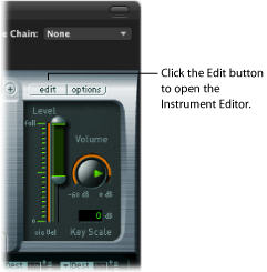
The Instrument Editor opens. When you play notes on the keyboard of the EXS24 mkII Instrument Editor, the notes are played on the selected channel strip. You can switch between Zones view and Groups view, click individual zones to view their parameters, click notes on the keyboard to hear the samples assigned to them, create zones and groups, and edit zone and group parameters just as you can in Logic Pro.
For in-depth information about using the EXS24 mkII Instrument Editor, refer to the Logic Pro Instruments manual.
Using Multiple Instrument Outputs in MainStage
MainStage supports the multiple output versions of the EXS24 mkII, Ultrabeat, and some Audio Units instruments. You can insert multi output instruments and use them to route different outputs to different physical outputs, apply different plug-ins or processing to different outputs, or for other uses.
If an instrument supports multiple outputs, one or more multi output versions are available in the Instrument Plug-in menu for the instrument.
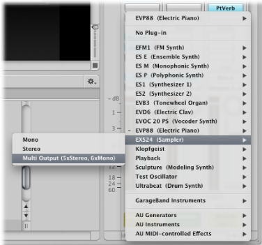
The Plug-in menu shows specific information about output configurations, for example: EXS24: Multi Output (5xStereo, 6xMono).
Note: Not all instruments support multiple outputs. If no multi output version is available in the Plug-in menu, the instrument does not support multiple outputs.
On the channel strip in which you want to use the multi output instrument, click the Instrument slot.
Choose the instrument from the Plug-in menu, and choose the multi output version from the submenu.
The instrument name appears in the Instrument slot, and a small Add (+) button appears below the Solo button on the channel strip. The Output for the instrument is set to Output 1-2.
Double-click the Instrument slot to open the instrument (plug-in) window.
You need to set up the output routing for individual sounds or samples in the instrument (plug-in window). You set up output routing for the EXS24 mkII in the Instrument Editor, and set up output routing for Ultrabeat in the Output menu of the Assignment section of the Ultrabeat window.
On the channel strip, click the Add button to add additional outputs.
Each time you add an output, a new section of the channel strip is added, with the next available pair of outputs.
Each output uses the same instrument, but each can have its own inserts, volume, pan, and expressions settings and its own effect sends, as well as its own outputs.
For more information about using multiple instrument outputs, see the Logic Pro User Manual and the Logic Pro Instruments manual. Information about specific instruments (for example, Ultrabeat) can be found in the chapters covering those instruments.
Using External MIDI Instruments in MainStage
You can add an external MIDI instrument channel strip to a patch and use it to play an external instrument, such as a hardware synthesizer. You can also use an external instrument to “play” a ReWire application.
When you use an external MIDI instrument channel strip, you choose the MIDI channel to send MIDI output from MainStage to the instrument, and choose the audio inputs to receive audio from the instrument. The audio output from the instrument is routed to the input of the channel strip, where you can process it using MainStage effects.
Click the Add Channel Strip (+) button in the upper-right corner of the Channel Strips area.
In the New Channel Strip dialog, select External Instrument.
You can also choose the MIDI input and output, the format, and the audio input and output for the channel strip. You can choose an audio channel or a ReWire application for the input, but cannot choose a bus. The MIDI input pop-up menu shows the Keyboard or MIDI Activity screen controls (which receive MIDI note input) currently in the workspace.
Note: When using an external instrument to send MIDI to a ReWire slave application (such as Reason or Live), you should disable any MIDI input the slave application receives directly from the hardware controller. For information about disabling MIDI input from a hardware device, consult the documentation for the application.
For ReWire applications, when you add an external channel strip, set the MIDI port to the ReWire slave. The Channel list also updates based on the port. Some ReWire slaves set up multiple ports. To use a ReWire application with MainStage, open the ReWire application after opening MainStage.
When you play your keyboard controller with the patch containing the external MIDI instrument selected, MainStage sends note and other MIDI messages to the chosen MIDI Output and MIDI Channel, receives audio from the chosen Input, and sends the audio output to the chosen Output. You can also send a program change message to the external instrument when you select the patch to control which program the external instrument uses.
In the Channel Strip Inspector, click the MIDI Out tab.
In the MIDI Out tab, select the Send Program Change checkbox.
The Program Change value is set to –1 by default, so that no program change is sent when you select the Send Program Change checkbox, until you change the value.
Set the program change number you want to send using the Send Program Change value slider.
If you want to send a Bank Change message, select the Send Program Change checkbox, then set the most-significant byte (MSB) and least-significant byte (LSB) of the bank change number using the Bank MSB and Bank LSB value sliders.
When you select the patch, the program change and bank change messages are sent to the external instrument. Also note that program and bank changes are sent when you edit the program change and bank change value sliders in the Channel Strip Inspector (so you can be sure that the values you enter send the correct program and bank change messages).
If you want the external instrument to respond to the program change, but do not want it to receive note or other MIDI information from your controller, click the MIDI Input tab and choose None from the Keyboard pop-up menu.
You can also use a knob or fader mapped to the Program Change action to send program changes to an external instrument.
In the workspace, click the screen control you want to use to send program change messages.
In the Screen Control Inspector, click the Unmapped tab.
In the Mapping browser, select the external instrument, then select MIDI Controller folder from the submenu.
In the third column from the left, select Program Change.
The screen control is mapped to the Program Change parameter. By moving the hardware control assigned to the screen control, you can send program changes to the external instrument.
Note: If the MIDI Out parameter of the external instrument channel strip is set to the external instrument when you map the screen control to the Program change parameter, a program change (Program 0) is sent when you create the mapping. If you are editing the program on the external instrument, your changes may be lost. To map the screen control without sending an immediate program change to the external instrument, choose None from the MIDI Out slot of the external instrument before you create the mapping, then choose the external instrument in the MIDI Out slot. No program change is sent until you move the knob or fader.
You can also send MIDI messages, including SysEx and continuous control messages, to your connected MIDI hardware devices using an external instrument channel strip. The Channel Strip inspector includes a Send MIDI File control where you can select a standard MIDI file with the information you want to send.
In the External Instrument Channel Strip inspector, click the MIDI Output tab.
Select the Send MIDI File checkbox, then click the Select button.
Browse to the location of the MIDI file you want to add, select the file, then click Send.
The MIDI file is sent immediately to the port selected on the external instrument channel strip. The MIDI file is re-sent on patch change just like the other options in the Channel Strip inspector (such as Program Change or MIDI Clock messages).
Only SMF (standard MIDI file) types 0 and 1 are supported. MIDI files are sent sequentially, one at at time, per concert. If you switch rapidly through several patches that send long MIDI files, the MIDI files are queued and sent in succession. MIDI messages are sent at the tempo stored in the MIDI file.
Using the Activity Monitor
As you work on your concert in Edit mode, the Activity Monitor in the toolbar shows the current CPU and memory information as well as received MIDI messages. The CPU section of the Activity Monitor glows red to indicate a CPU overload condition.
The Memory section of the Activity Monitor glows yellow to indicate a low-memory condition. Low-memory conditions can be caused by having too many memory-intensive channel strips or plug-ins in a concert or by using other memory-intensive applications (including ReWire applications) together with the concert. If a low-memory condition occurs, try reopening the concert and consolidating some memory-intensive plug-ins or channel strips.