EVOC 20 Filterbank
The EVOC 20 Filterbank consists of two formant filter banks. The input signal passes through the two filter banks in parallel. Each bank features level faders for up to 20 frequency bands, allowing independent level control of each band. Setting a level fader to its minimum value completely suppresses the formants in that band. You can control the position of the filter bands with the Formant Shift parameter. You can also crossfade between the two filter banks.
Getting to Know the EVOC 20 Filterbank Interface
The EVOC 20 Filterbank interface is divided into three main sections: the Formant Filter parameters section in the center of the window, the Modulation parameters section at the bottom center, and the Output parameters section along the right side.
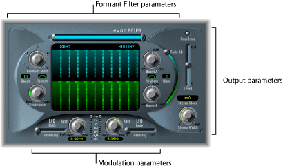
- Formant Filter parameters: Control the frequency bands in the two filter banks: Filter Bank A (top, blue) and Filter Bank B (bottom, green). See EVOC 20 Filterbank Formant Filter Parameters.
- Modulation parameters: Control how Formant Filter parameters are modulated. See EVOC 20 Filterbank Modulation Parameters.
- Output parameters: Control the overall output level and panning of the EVOC 20 Filterbank. See EVOC 20 Filterbank Output Parameters.
EVOC 20 Filterbank Formant Filter Parameters
The parameters in this section provide precise level and frequency control of the filters.
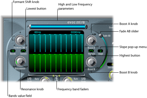
- High and Low Frequency parameters: Determine the lowest and highest frequencies allowed to pass by the filter banks. Frequencies that fall outside these boundaries will be cut.
The length of the horizontal blue bar at the top represents the frequency range. You can move the entire frequency range by dragging the blue bar. The silver handles on either end of the blue bar set the Low Frequency and High Frequency values, respectively.
You can also use the numeric fields to adjust the frequency values separately.
- Boost A and B knobs: Set the amount of boost—or cut—applied to the frequency bands in Filter Bank A or B. This allows you to compensate for the reduction in volume caused by lowering the level of one or more bands. If you use Boost to set the (level) mix relationship between the filter banks, you can use Fade A/B (see “Fade AB slider” below) to alter the tonal color, but not the levels.
EVOC 20 Filterbank Modulation Parameters
The Modulation section offers two LFOs. The LFO Shift parameters on the left side control the Formant Shift parameter. The LFO Fade parameters on the right side control the Fade AB parameter.
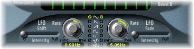
- Rate knobs and fields: Determine the speed of modulation. Values to the left of the center positions are synchronized with the host application tempo and include bar values, triplet values, and more. Values to the right of the center positions are non synchronized and are displayed in Hertz (cycles per second).
Note: The ability to use synchronous bar values could be used to perform a formant shift every four bars on a cycled one-bar percussion part, for example. Alternately, you could perform the same formant shift on every eighth-note triplet within the same part. Either method can generate interesting results, and can lead to new ideas, or add new life to old audio material.
- Waveform buttons: Set the waveform type used by the Shift LFO on the left side or Fade LFO on the right side. You can choose between triangle, falling and rising sawtooth, square up and down around zero (bipolar, good for trills), square up from zero (unipolar, good for changing between two definable pitches), a random stepped waveform (S&H), and a smoothed random waveform for each LFO.
- LFO Fade Intensity slider: Controls the amount of Fade AB modulation by the Fade LFO.
Tip: LFO modulations are the key to some extraordinary effects that can be obtained with the EVOC 20 Filterbank. Set up either completely different or complementary filter curves in both filter banks. You can use rhythmic material—such as a drum loop—as an input signal, and set up tempo-synchronized modulations, with different rates for each LFO. Feel free to try a tempo-synchronized delay effect—such as Tape Delay—after the EVOC 20 Filterbank to produce unique polyrhythms.
EVOC 20 Filterbank Output Parameters
The Output parameters provide control over the level and stereo width. The Output section also incorporates an integrated overdrive (distortion) circuit.
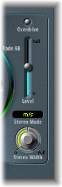
- Stereo Mode pop-up menu: Sets the input/output mode of the EVOC 20 Filterbank. The choices are m/s (mono input/stereo output) and s/s (stereo input/stereo output).
In s/s mode, the left and right channels are processed by separate filter banks.
In m/s mode, a stereo input signal is first summed to mono before being routed to the filter banks.
- Stereo Width knob: Distributes the output signals of the filter bands in the stereo field.
At the left position, the outputs of all bands are centered.
At the centered position, the outputs of all bands ascend from left to right.
At the right position, the bands are output—alternately—to the left and right channels.