Using Oscillator 1 in Ultrabeat
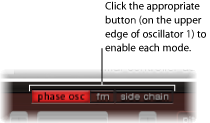
Oscillator 1 can be switched between three different modes. In essence, this enables different types of synthesis engines: phase oscillator, fm, and side chain (external audio input), which extends your sonic palette significantly. Each mode offers different parameters and features.
Using Oscillator 1’s Phase Oscillator Mode in Ultrabeat
The waveform of the phase oscillator can be reshaped into almost any basic synthesizer waveform. The effect of parameter changes are immediately reflected in the waveform display within the Oscillator section.
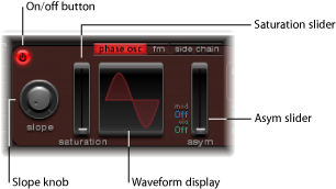
- Slope knob: Determines the slope or steepness of the waveform. The higher the value, the steeper the waveform. The resulting sound takes on an increasingly nasal character as the incline becomes more vertical.
- Saturation slider: Increases the gain, eventually causing the waveform to clip. Higher values result in a distortion of the waveform shape, making it more rectangular. This results in a corresponding increase in odd-numbered overtones.
- Asym(metry) slider: Changes the waveform angle. Higher values skew the waveform toward a sawtooth wave, making the sound more edgy. Asym can be modulated by the sources found in the “mod” and “via” menus. This allows you to create dynamic sound changes at the oscillator level. For more information, see Working with Modulation in Ultrabeat.
Creating Classic Waveforms in Ultrabeat’s Phase Oscillator Mode
The basic waveforms of classic analog synthesizers can be easily reproduced with the phase oscillator: sine, rectangular, and sawtooth waves will result from different Slope, Saturation, and Asym parameter value combinations.
For example, setting Slope and Saturation to their maximum values, and Asym to the minimum value will result in a classic square wave. Setting Slope to −0.20, Saturation to the minimum, and Asym to the maximum value, will result in a sawtooth wave. Setting all three parameters to 0 values will cause the oscillator to produce a sine wave. See the table below for an overview of the tonal qualities of each basic waveform.
Waveform | Basic tone | Comments |
|---|---|---|
Rectangular | Nasal sounding | Great for reed instruments, synth blips, basses |
Square | Hollow and woody sounding | Useful for basses, clarinets, and oboes. The pulse width of (oscillator 2 and 3) square waveforms can be smoothly scaled between 50% and the thinnest of pulses. |
Sawtooth | Warm and even | Useful for strings, pads, bass, and brass sounds |
Triangle | Sweet sounding, softer than sawtooth | Useful for flutes, pads |
Sine | A pure tone | The sine wave of Oscillator 1 can be frequency-modulated by Oscillator 2. This kind of frequency modulation forms the basis of FM synthesis. |
Using Ultrabeat’s FM (Frequency Modulation) Mode
Whereas the phase oscillator is well suited to simulations of analog waveforms and analog-style sounds, FM mode is well suited to the creation of bell-like digital tones and metallic sounds.
The principle of frequency modulation (FM) synthesis was developed in the late 1960s and early 1970s by John Chowning. It was popularized by Yamaha’s range of DX synthesizers in the 1980s. Ultrabeat can’t be compared with the DX series in the discipline of pure FM synthesis, but it can certainly achieve some of the signature sounds of these instruments.
How Frequency Modulation Works
Put very simply, the frequency of one signal generator (oscillator) is altered, or modulated, by another signal generator. Positive, or higher, frequency values from the second generator, known as themodulator, increase the frequency of the first generator, known as thecarrier. Negative, or lower, frequency values from the second generator decrease the frequency of the first.
In a synthesizer, this type of modulation takes place in the audio spectrum. Depending on the design of the instrument, you can hear the signals of either the carrier alone, being modulated by the modulator, or both oscillators. The interaction between the two oscillators alters the waveform signal of the carrier and introduces a number of new harmonics. This harmonic spectra can then be used as the source signal for further sound processing, such as filtering, envelope control, and so on. For further information, see Frequency Modulation (FM) Synthesis and EFM1.
Frequency Modulation in Ultrabeat
In FM mode, Oscillator 1 (the carrier) generates a sine wave. Its frequency is modulated by the waveform of Oscillator 2 (the modulator).
When Oscillator 2 outputs a positive (or higher) frequency signal, the frequency of Oscillator 1 increases.
When Oscillator 2 outputs a negative (or lower) frequency signal, the frequency of Oscillator 1 decreases.
The net effect of speeding up or slowing down the frequency of Oscillator 1 in each waveform cycle is a distortion of the basic wave shape. This waveform distortion also has the side benefit of introducing a number of new, audible, harmonics.
The more complex the Oscillator 2 waveform, the more partials will be created by increasing the FM Amount during the FM process. Keep an eye on the display to see how the sine wave takes on an increasingly complex shape.
Note: Oscillator 2 must be enabled if you want to use frequency modulation.
Important: The impact of any frequency modulations you may perform depends onboth the frequency ratio and the modulation intensity of the two oscillators.
Adjust the Pitch parameter values of one, or both, oscillators.
Adjust the amount (intensity) of frequency modulation with the FM Amount knob.
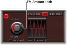
This parameter can be modulated by the sources found in the “mod” and “via” menus. For more information, see Working with Modulation in Ultrabeat.
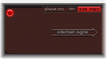
Using Ultrabeat’s Side Chain Mode
In Side Chain mode, Ultrabeat uses an external side-chain input as the source for Oscillator 1. This means that you can send the signal of any audio channel strip, any bus, or live input through Ultrabeat’s filters, envelopes, LFO, and step sequencer. Using busses as sidechain sources makes it possible to route signals to the sidechain input from any channel strip type that offers busses as outputs or sends. This includes software instrument channel strips, aux channel strips, or a mix of multiple channel strips that are routed into a common aux (sub group), that has a bus as the output destination.
Here is an example of how you might take advantage of this feature: You could use an audio input from Oscillator 1, along with the synthesis engine of Oscillator 2, to create a part live audio, part synthesized drum sound.
Note: The side chain affects only the selected drum sound—Ultrabeat’s other drum sounds and sequences behave as usual.
Here is another example of where this could be useful: You could use one drum sound in a kit to filter an external audio signal with a programmed groove.
Note: A side chain audio signal alone is not enough to trigger Ultrabeat. To hear the side-chained audio signal, Ultrabeat needs to be triggered by MIDI or the internal step sequencer.
Activate the “side chain” button for Oscillator 1.
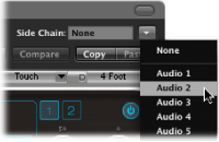
Choose the channel strip that you want to use as the side chain input source from the Side Chain pop-up menu at the top of the plug-in window.