Working with EXS24 mkII Modulation
The EXS24 mkII is equipped with an extensive range of modulation sources and destinations, making it a very flexible instrument that can generate extraordinary sounds that constantly evolve, or are just plain expressive to play. Reference tables that cover all modulation destinations and sources are found at the end of this section.
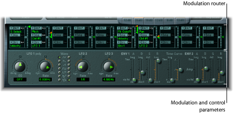
- Modulation router: The modulation router—abbreviated to router—links modulation sources, such as the envelope, to modulation destinations, such as the filter. The router features ten modulation routings—arranged into columns. See Getting to Know the EXS24 mkII Modulation Router.
- Modulation and control parameters: These include the LFOs and envelopes. See Getting to Know the EXS24 mkII LFOs and Getting to Know the EXS24 mkII Envelopes (ENV 1 and ENV 2).
Getting to Know the EXS24 mkII Modulation Router
The modulation router spans the center of the EXS24 mkII interface. If you are new to synthesizer modulation routings, see Modulation Routing in Synthesizer Basics. Also see An EXS24 mkII Modulation Example.
Any modulation source can be connected to any modulation destination—much like an old-fashioned telephone exchange or a studio patch bay. See Creating and Bypassing EXS24 mkII Modulation Routings, EXS24 mkII Modulation Source Reference, and EXS24 mkII Modulation Destination Reference.
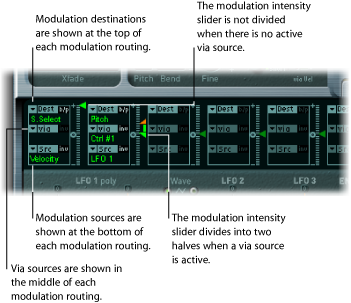
The modulation intensity—how strongly the destination is influenced by the source—is set with the vertical slider to the right of the modulation routing.
The intensity of the modulation can itself be modulated: The via parameter defines a further modulation source, which is used to control the modulation intensity. When via is active, you can specify upper and lower limits for the modulation intensity. See Using EXS24 mkII Via Sources to Control Modulation Intensity and EXS24 mkII Modulation Via Source Reference.
Ten such modulation routings of source, via, and destination can take place simultaneously, in addition to routings that are hard-wired outside of the router. It does not matter which of the ten modulation routings you use.
You can even select the same destination in several parallel modulation routings. You can also use the same sources and the same via controllers in multiple modulation routings.
Creating and Bypassing EXS24 mkII Modulation Routings
The following information applies to all ten modulation routings.
Open the Dest pop-up menu to see all available destinations, and choose the parameter you want to modulate.
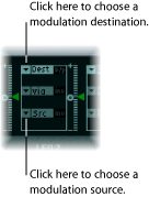
Open the Src pop-up menu to see all available sources, and choose the parameter you want to use to modulate the destination.
Vertically drag the arrowhead of the Intensity slider to the right of the modulation routing to set a fixed modulation intensity.

Click the “b/p” button at the top right of the modulation routing.
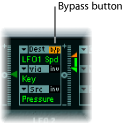
The Bypass (b/p) parameter allows you to enable or disable individual modulation routings, without losing settings.
Using EXS24 mkII Via Sources to Control Modulation Intensity
In a basic modulation routing consisting of a destination and source, you can set a fixed modulation intensity by vertically dragging the arrowhead of the Intensity slider to the right of the routing. The slider value always defines a constant modulation intensity.
The intensity of the modulation can itself be modulated: The via parameter defines a further modulation source, which is used to control the modulation intensity. As soon as you choose a value other than off for “via,” the Intensity slider is divided into two halves, each half with its own arrowhead.
The lower half defines the minimum modulation intensity, when the via controller—the modulation wheel, for example—is set to its minimum value.
The upper half defines the maximum modulation intensity when the via controller is set to its maximum value.
The area between the two slider halves defines the modulation range of the via controller.
Open the Dest pop-up menu to see all available destinations, and choose the parameter you want to modulate.
Open the Src pop-up menu to see all available sources, and choose the parameter you want to use to modulate the destination.
Open the via pop-up menu to see all available sources, and choose the source you want to use for control of the modulation intensity.
Vertically drag the upper arrowhead of the Intensity slider, to the right of the modulation routing, to set the maximum modulation intensity.

Vertically drag the lower arrowhead of the Intensity slider to set the minimum modulation intensity.

Drag the range area between the two slider halves vertically.

Both arrowheads will move simultaneously.
If this area is too small to drag, just drag an unused section of the Intensity slider control to move the area.
Click the small 0 symbol that is halfway up the Intensity slider control.

Click the “inv” button to the right of the via pop-up menu.

An EXS24 mkII Modulation Example
The following example is useful for string sound modulations, where playing higher notes results in a faster modulation.

LFO1 Speed is the modulation destination.
The modulation source—Pressure—is used to modulate the speed (Rate) of LFO 1.
You’ll hear a faster modulation as you apply more pressure to the keyboard—after the initial keystrike.
The modulation intensity is controlled by keyboard position, the range of which is determined by the via parameter. In other words, the note (number) that you play controls the depth of LFO speed modulation.
Getting to Know the EXS24 mkII LFOs
The EXS24 mkII includes three LFOs (low frequency oscillators) that can be used as modulation sources. They are all available as sources or destinations in the router. If you are new to synthesizers, and the concept behind LFOs, see Using the LFO to Modulate Sounds.
LFO 1 is polyphonic, which means that if it is used for any modulation of multiple voices, they will not be phase-locked. Furthermore, LFO 1 is key-synced: Each time you play a key, the LFO 1 modulation of this voice is started from zero.
To understand the non-phase-locked characteristic more fully, imagine a scenario where a chord is played on the keyboard. If LFO 1 is used to modulate pitch, for example, the pitch of one voice might rise, the pitch of another voice might fall, and the pitch of a third voice might reach its minimum value. As you can see, the modulation is independent for each voice, or note.
The key sync facility ensures that the LFO waveform cycle always starts from zero, which results in consistent modulation of each voice. If the LFO waveform cycles were not synchronized in this way, individual note modulations would be uneven.
LFO 1 can also be faded in or out automatically, courtesy of a built-in envelope generator.
LFO 2 is monophonic, which means that the modulation is identical for all voices. To understand this more fully, imagine a scenario where a chord is played on the keyboard. If LFO 2 is used to modulate pitch, for example, the pitch of all voices in the played chord will rise and fall synchronously.
LFO 3 is also monophonic. It always uses a triangular waveform.
All three LFOs can oscillate freely, or can be synchronized to the host application tempo, in values ranging between 32 bars and 1/128 triplets.
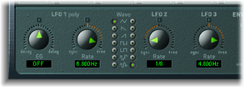
- LFO 1 EG knob: Controls the time it takes for the LFO modulation to fade in or fade out (see Using the EXS24 mkII Envelope Generator of LFO 1).
- LFO 1 and 2 Wave buttons: This is where you choose the desired waveform for LFO 1 and LFO 2. For details about how to use them, see Using EXS24 mkII LFO Waveforms.
- LFO 2 Rate knob: This parameter defines the frequency—the speed—of the LFO 2 modulation. See Setting the EXS24 mkII LFO Rate.
- LFO 3 Rate knob: This parameter defines the frequency—the speed—of the LFO 3 modulation. See Setting the EXS24 mkII LFO Rate.
Using EXS24 mkII LFO Waveforms
The Wave buttons allow you to choose different waveforms for LFO 1 and LFO 2. The table below outlines how these can affect your sounds.
Tip: Try different waveforms while a modulation routing of Pitch is engaged and running.
Waveform | Comments |
|---|---|
Triangle | Well suited for vibrato effects |
Sawtooth | Well suited for helicopter and space gun sounds. Intense modulations of pitch with a negative (inverse) sawtooth wave lead to “bubbling” sounds. Intense sawtooth modulations of lowpass filter cutoff and resonance create rhythmic effects. The waveform can also be inverted, resulting in a different start point for the modulation cycle. |
Rectangle | Use of the rectangular waves will periodically switch the LFO between two values. The upper rectangular wave switches between a positive value and zero. The lower wave switches between a positive and a negative value set to the same amount above/below zero.An interesting effect you may want to try out is achieved by modulating the Pitch destination with a suitable modulation intensity that leads to an interval of a fifth. Choose the upper rectangular wave to do so. |
Sample & Hold | The two lower waveform settings of the LFOs output random values. A random value is selected at regular intervals, as defined by the LFO rate. The upper waveform steps between randomized values (rapid switches between values). At its lower setting, the random wave is smoothed out, resulting in fluid changes to values. The term Sample & Hold (S & H) refers to the procedure of taking samples from a noise signal at regular intervals. The values of these samples are then held until the next sample is taken.Tip: A random modulation of Pitch leads to an effect commonly referred to as a random pitch pattern generator or sample and hold. Try using very high notes, at very high rates and high intensities—you’ll recognize this well-known effect from hundreds of science fiction movies! |
Using the EXS24 mkII Envelope Generator of LFO 1
LFO 1 features a simple envelope generator that is used to control the time it takes for the LFO modulation to fade in or fade out. At its center position, which can be accessed by clicking the middle mark, the modulation intensity is static—no fade-in or fade-out will occur.
Choose a positive LFO 1 EG knob value to fade in the modulation.
The higher the value, the longer the delay time.
Choose a negative LFO 1 EG value to fade out the modulation.
The lower the value, the shorter the fade-out time.
LFO envelopes are most often used for delayed vibrato—many instrumentalists and singers intonate longer notes this way.
Place the LFO 1 EG knob at a position towards the right (Delay) and modulate the Pitch destination with the LFO1 source in the router.
Set a slight modulation intensity.
Select an LFO 1 Rate of about 5 Hz.
Choose the triangular wave as the LFO 1 waveform.
Tip: Chaotic and fast modulations of frequencies (destination: Pitch) by the LFO 1 source—with a delayed Sample & Hold waveform, a high Rate, and short fade-out—are ideal for emulating the attack phase of brass instruments.
Setting the EXS24 mkII LFO Rate
LFO 2 is ideally suited for creating rhythmic modulation effects—effects that retain perfect synchronicity, even during project tempo changes. LFO 3 is much the same, but uses a fixed triangle waveform, making it most suitable for adding vibrato to a sound, or for use as a modulation source for the other LFOs.
The Rate parameter of all three LFOs allows the respective LFO to run freely (in the right-hand side of the Rate knob range), or to be synchronized with the project tempo (in the left-hand side of the Rate knob range).
The rate is displayed in Hertz or rhythmic values—the latter when project tempo synchronization is active. Rates range from speeds of 1/64-notes to a periodic duration of 32 bars. Triplet and punctuated values are also available.
Getting to Know the EXS24 mkII Envelopes (ENV 1 and ENV 2)
The EXS24 mkII features two envelope generators per voice. They are abbreviated as ENV 1 and ENV 2 in the interface and router. For details on the roots of the term envelope generator and its basic functionality, see Envelopes in the Amplifier Section.
The parameters of ENV 1 and ENV 2 are identical.
ENV 1 controls the filter over time.
ENV 2 defines the changes in level over time—for each note played.
Both envelopes, however, are also available for simultaneous use as sources in the router. The envelope time parameters (Attack, Decay, and Release) are also available as modulation destinations in the router.
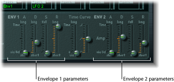
- A(ttack) slider: Defines the time it takes for the level of a note to rise from an amplitude of zero to the set amplitude. The Attack time sliders of both envelopes are divided into two halves.
The lower half defines the attack time when the keys are struck hard, at maximum velocity. The upper half defines the attack time at minimum velocity. Drag the area between the two slider halves to move them both simultaneously. If this area is too small to drag, drag an unused portion of the slider control.
- D(ecay) slider: Determines the time it takes for the level of a held note to fall to the sustain level after the attack phase has completed.
If the Sustain level parameter is set to its maximum value, the Decay parameter has no effect.
When the Sustain level is set to its minimum value, the Decay parameter defines the duration or fade-out time of the note.
- Time Curve sliders: These apply to both envelopes. The left slider, known as time via key, can be used to scale (lengthen or shorten) the envelope time intervals. Note that position C3 is the center point.
Time intervals for zones assigned to keys above C3 can be reduced in length with the left slider. All time intervals for zones assigned to keys below C3 can be lengthened.
The (Attack) Curve slider determines the shape of the envelope attack curve.
EXS24 mkII Modulation Destination Reference
The following destinations are available for real-time modulation.
Destination | Comments |
|---|---|
Sample Select | Modulates the sample (zone) that is played. By default, Sample Select is controlled by velocity—through the default Velocity to Sample Select modulation routing. This means that the received note velocity value determines which of the layered zones (in different velocity ranges) is heard as you play the keyboard softer or harder. You aren’t limited to using velocity, however, to determine which sample is played. You could assign the modulation wheel source to the Sample Select destination, or use both velocity and the modulation wheel. If you choose a continuous controller such as the modulation wheel, you can step through the velocity layers during playback. In this case, make use of the crossfade (Xfade) parameters to create smooth transitions between velocity split points. When using multiple modulation sources, be aware that these can cause all velocity layers to run simultaneously—using up as many voices as there are layered zones. The CPU usage will increase accordingly. |
Sample Start | Modulates the sample start time. This allows you to trigger a drum loop, partway through, for example. |
Glide Time | Modulates the duration of the Glide (portamento) effect. If you modulate Glide, with Velocity selected as the source, the speed of the keystrike determines the time it takes for the played notes to reach the target pitch. |
Pitch | Modulates the frequency (pitch) of the loaded sampler instrument. If you select an LFO as the source, this destination leads to siren or vibrato sounds. Select one of the envelope generators with zero attack, short decay, zero sustain, and short release as the source for tom and kick drum sounds. Slight envelope modulations can make the amount of detuning change over time, which can be particularly useful for brass sounds. |
Filter Drive | Modulates the filter Drive parameter. |
Filter Cutoff | Modulates the Cutoff Frequency parameter. See Working with EXS24 mkII Filter Parameters. |
Filter Resonance | Modulates the Resonance parameter of the filter. |
Volume | Controls the main output level of the EXS24 mkII. |
Pan | Modulates the panorama position of the sound in the stereo spectrum. Modulating Pan with an LFO will result in a stereo tremolo (auto panning). In unison mode, the panorama positions of all voices are spread across the entire stereo spectrum. Nevertheless, pan can still be modulated, with positions being moved in parallel. |
Relative Volume | Adds/subtracts the specified amount to/from the Volume parameter. |
LFO 1 Dcy./Dly (LFO 1 Decay/Delay) | Controls the LFO 1 EG parameter (see Using the EXS24 mkII Envelope Generator of LFO 1). |
LFO 1 Speed | Modulates the frequency (rate) of LFO 1. You can automatically accelerate/slow down LFO 1’s rate by modulating the LFO1 Speed destination with one of the envelope generators (ENV) or with LFO2 or LFO 3. |
LFO 2 Speed | As above, for LFO 2 |
LFO 3 Speed | As above, for LFO 3 |
Env 1 Attack | Modulates the Attack time of the filter envelope. |
Env 1 Decay | Modulates the Decay time of the filter envelope. |
Env 1 Release | Modulates the Release time of the filter envelope. |
Time | Modulates the time via key slider position—see Time Curve sliders description in Getting to Know the EXS24 mkII Envelopes (ENV 1 and ENV 2). |
Env 2 Attack (Amp) | Modulates the Attack time of the second envelope generator. |
Env 2 Decay (Amp) | Modulates the Decay time of the second envelope generator. In cases where you’ve selected Env 2 Decay as the destination and Velocity as the source, the duration of the decaying note is dependent on how hard you strike the key. Selecting Key(board) as the source will result in higher notes decaying more quickly (or slowly). |
Env 2 Release (Amp) | Modulates the Release time of the second envelope generator. |
Hold | Modulates the (alternate) controller assigned to the sustain pedal function. See the Hold parameter information in Adjusting EXS24 mkII Global Parameters. |
EXS24 mkII Modulation Source Reference
The following modulation sources are available:
Source | Comments |
|---|---|
Side Chain | Side Chain modulation uses a side chain signal as a modulation signal. The side chain source can be selected in the Side Chain menu in the header of the plug-in window. It is fed to the internal envelope follower, which creates a modulation value based on the current side chain input signal level. |
Maximum | Max sets the value of this source to +1 (an internal value that indicates the maximum possible amount for this source). This offers interesting options for controlling the modulation intensity with all possible via values. |
ENV 1 | Envelope Generator 1 is used as a source. |
ENV 2 (Amp) | Envelope Generator 2 is used as a source. Env 2 always controls the level of the overall sound. |
LFO 1 | LFO 1 is used as a source. |
LFO 2 | As above, but for LFO 2 |
LFO 3 | As above, but for LFO 3 |
Release Velocity | The modulation occurs when you release a key (this requires a keyboard that sends release velocity information). |
Pressure | Pressure (also known as Aftertouch) serves as a modulation source. The EXS24 mkII reacts to poly pressure (polyphonic aftertouch).Note: If you set the destination to Cutoff, the cutoff frequencies will rise and fall, dependent on how firmly you press a key on your touch-sensitive MIDI keyboard—after the initial keystrike. |
Pitch Bend | The pitch bend wheel is used as a modulation source. |
Key | Kybd (Keyboard) outputs the keyboard position (the MIDI note number). The center point is C3 (an output value of 0, used internally by the EXS24 mkII). An output value of −1 indicates five octaves below (the center point). An output value of +1 indicates five octaves above. Modulate the Cutoff destination with the Key source to control the cutoff frequencies of the filter with the keyboard position—as you play up and down the keyboard, the cutoff frequencies change. A modulation intensity of 0.5 proportionately scales cutoff frequencies with keyboard note pitches. |
Velocity | Velocity serves as a modulation source. |
--- | Disables the source. |
MIDI Controllers 1–120 | The chosen MIDI controller serves as a modulation source. Controllers 7 and 10 are marked as (not available). Host applications use these controllers for volume and pan automation of channel strips. Controller 11 is marked as (Expression). It has a fixed connection to this functionality, but it can also be used to control other modulation sources. |
EXS24 mkII Modulation Via Source Reference
The following sources may be used to control the modulation intensity.
via Source | Comments |
|---|---|
Side Chain | Side Chain modulation uses a side chain signal as a modulation intensity (trigger) signal. The side chain source can be selected in the Side Chain menu in the header of the plug-in window. It is fed to the internal envelope follower, which creates a modulation value based on the current side chain input signal level. |
Maximum | Sets the value of this source to +1. |
ENV 1 | Envelope Generator 1 controls the modulation intensity. |
ENV 2 (Amp) | Envelope Generator 2 controls the modulation intensity. |
LFO 1 | The modulation undulates at the speed and waveform of LFO 1, which controls the modulation intensity. |
LFO 2 | As above, but for LFO 2 |
LFO 3 | As above, but for LFO 3 |
Release Velocity | The modulation will be more or less intense dependent on how quickly you release the key (this requires a keyboard that sends release velocity information). |
Pressure | If you select Pressure (also known as Aftertouch) as the via value, the modulation intensity will be touch sensitive—modulation will be more or less intense dependent on how firmly you press the key of your touch-sensitive MIDI keyboard after the initial keystrike. |
Pitch Bend | The pitch bend wheel controls the modulation intensity. |
Key | Key(board) outputs the keyboard position (the MIDI note number). The center point is C3 (an output value of 0). Five octaves below and above, an output value of −1 or +1, respectively is sent. If you select Pitch as the destination, modulate it with the LFO1 source, and select Key as the via value, the vibrato depth will change, dependent on key position. Put another way, the vibrato depth will be different for notes higher or lower than the defined Key(board) position. |
Velocity | The modulation intensity will be velocity sensitive—modulation will be more or less intense depending on how quickly (hard) you strike the key. |
--- | Disables the via source. |
MIDI Controllers 1–120 | Modulation intensity is determined by the chosen MIDI controller value. Controllers 7 and 10 are marked as (not available). Host applications use these controllers for volume and pan automation of channel strips. Controller 11 is marked as (Expression). It has a fixed connection to this functionality, but it can also be used to control other modulation sources. |