Clip Distortion

Clip Distortion is a nonlinear distortion effect that produces unpredictable spectra. It can simulate warm, overdriven tube sounds and can also generate drastic distortions.

Clip Distortion features an unusual combination of serially connected filters. The incoming signal is amplified by the Drive value, passes through a highpass filter, and is then subjected to nonlinear distortion. Following the distortion, the signal passes through a lowpass filter. The effect signal is then recombined with the original signal and this mixed signal is sent through a further lowpass filter. All three filters have a slope of 6 dB/octave.

This unique combination of filters allows for gaps in the frequency spectra that can sound quite good with this sort of nonlinear distortion.

Figure. Clip Distortion window.
  • Drive slider and field: Sets the amount of gain applied to the input signal. After being amplified by the Drive value, the signal passes through a highpass filter.
  • Tone slider and field: Sets the cutoff frequency (in Hertz) of the highpass filter.
  • Clip Circuit display: Shows the impact of all parameters, with the exception of the High Shelving filter parameters.
  • Symmetry slider and field: Sets the amount of nonlinear (asymmetrical) distortion applied to the signal.
  • Clip Filter slider and field: Sets the cutoff frequency (in Hertz) of the first lowpass filter.
  • Mix slider and field: Sets the ratio between the effect (wet) signal and original (dry) signals, following the Clip Filter.
  • Sum LPF knob and field: Sets the cutoff frequency (in Hertz) of the lowpass filter. This processes the mixed signal.
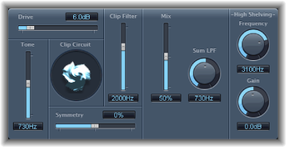
  • (High Shelving) Frequency knob and field: Sets the frequency (in Hertz) of the high shelving filter. If you set the High Shelving Frequency to around 12 kHz, you can use it like the treble control on a mixer channel strip or a stereo hi-fi amplifier. Unlike these types of treble controls, however, you can boost or cut the signal by up to ±30 dB with the Gain parameter.
  • (High Shelving) Gain knob and field: Sets the amount of gain applied to the output signal.
  • Input Gain field and slider (Extended Parameters area): Sets the amount of gain applied to the input signal.
  • Output Gain field and slider (Extended Parameters area): Sets the amount of gain applied to the output signal.