Setting Control Surfaces Preferences
Various settings that affect the onscreen appearance and performance of control surfaces can be made in the Logic Pro Control Surfaces preferences.
Choose Logic Pro > Preferences > Control Surfaces > Preferences (or use the Open Control Surfaces Preferences key command).
Choose Logic Pro > Preferences > Control Surfaces > Bypass all Control Surfaces.
This command is useful for silencing motorized control surface faders when recording in the same room. It is also handy when troubleshooting MIDI data errors, or for reducing MIDI bandwidth requirements.
General Preferences
General control surface preferences include resolution of relative controls, maximum MIDI bandwidth, and other functions.
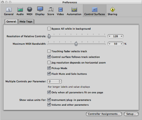
- “Bypass All while in background” checkbox: Allows you to share your control surface with other applications, when Logic Pro is not the active program.
- Resolution of Relative Controls slider: Sets the resolution of controls that change values in a relative manner. The default resolution is 128 steps. Choose a higher resolution value to divide the value range into finer increments.
- Maximum MIDI Band Width slider: Drag to set the maximum amount of MIDI bandwidth that your control surface can use. This is set to a default of 50%, which should be suitable for most situations. You can adjust the value if you find that your MIDI or automation playback is being affected.
- “Touching fader selects track” checkbox: When this option is selected, touching a fader on the control surface selects the track corresponding to the fader. For this to work, the device must feature touch-sensitive faders.
- “Control surface follows track selection” checkbox: When this checkbox is selected, selecting a track in the Arrange window automatically selects the corresponding track or channel on the control surface.
- “Jog resolution depends on horizontal zoom” checkbox: When selected, the precision of scrubbing (using the Jog/Shuttle Wheel of your control surface) is determined by the horizontal zoom level of Logic Pro. Your control surface must feature a Jog/Shuttle Wheel (or similar control) for this to have any effect. To retain a consistent resolution, regardless of Logic Pro window zoom levels, deselect this checkbox.
- Pickup Mode checkbox: When selected, the control surface operates in Pickup mode (if this mode is available). Some control surfaces, typically those without motorized faders or knobs, do not show parameter changes—caused by playing back existing automation data—on their interface. Such control surfaces usually offer a Pickup mode. In Pickup mode, the controller must reach (“pick up”) the current value before the value starts to change. This prevents sudden jumps of parameter values caused by playing back automation. Your device may feature a display (usually a pair of arrow LEDs) that indicates the direction or distance you need to move the controller, in order to match the settings shown in Logic Pro (also known as NULL). Once you have matched the onscreen values, deactivate Pickup mode and start automating.
When Pickup mode is turned off, adjusting a fader modifies the parameter immediately (which can result in parameter value jumps).
- Flash Mute and Solo buttons checkbox: When selected, the Mute and Solo buttons on the control surface will blink (flash) on and off when mute or solo modes are engaged.
- Multiple Controls per Parameter pop-up menu: Choose the maximum number of encoders used for each parameter, when editing plug-ins or audio instruments. The choices are:
- 1: Parameters are always displayed using one encoder per parameter, with the least space available for parameter name and value in the LCD.
- 2: On each unit, encoders 1 and 2 are used for the first parameter, encoders 3 and 4 for the second, and so on.
- 4: On each unit, encoders 1 to 4 are used for the first parameter, encoders 5 to 8 for the second, and so on.
- 8: On each unit, encoders 1 to 8 are used for the first parameter, encoders 9 to 16 for the second, and so on.
When multiple encoders are used per parameter, the encoders are divided into groups (1/2, 3/4, 5/6, 7/8, for example). The first encoder of each group controls the parameter shown in the display. The remaining encoders are inactive.
Using more than one encoder per parameter shows fewer parameters at any given time, but you gain space on the LCD to cater to longer parameter names and values. The more control surfaces you have within a control surface group, the more you benefit from this feature.
- “Only when all parameters fit in one page” checkbox: When selected, the defined number of encoders are only used when there are sufficient encoders available to show all parameters, without changing pages. For example, if you have a Mackie Control and two Mackie Control XTs (giving you at total of 24 encoders), a plug-in with 13 parameters will be shown with one encoder per parameter. Eleven encoders will remain unused. A plug-in with 11 parameters will be shown with two encoders per parameter. Two encoders will remain unused (as will the inactive encoders of the subdivisions mentioned above).
When deselected, multiple encoders are used for each parameter, which may require scrolling. This would not be the case if only one encoder were used for each parameter.
- “Show value units for” checkboxes: The two checkboxes in this section allow you to adjust whether parameter values are appended by the measurement unit, where applicable—“Hz” or “%,” for example. You can set this option separately for instrument and plug-in parameters, and for volume and other channel strip parameters. When selected, applicable values are appended with the appropriate unit. Turn off this option if viewing units makes the display too cluttered.
- Controller Assignments button: Click to open the Controller Assignments window.
- Setup button: Click to open the Control Surfaces Setup window.
Help Tags Preferences
For control surfaces that feature freely programmable displays with more than six characters per line (or segment) of the display, you can change the way help tags are shown. Control surface help tags are similar to Logic Pro help tags, showing additional information during use.
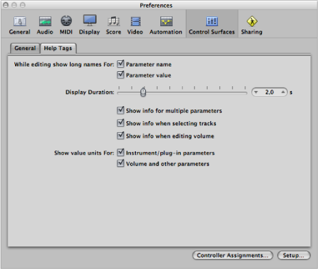
- “While editing show long names for” checkboxes: The two checkboxes in this section allow you to set how the names and values of parameters are displayed on the LCD of the control surface.
- “Parameter name” checkbox: When selected, the upper LCD line displays the full parameter name, rather than an abbreviated form of it, when you edit a parameter.
- “Parameter value” checkbox: When selected, the lower LCD line displays the full parameter value when you edit a parameter. If the “Show value units for parameter” checkboxes (see below) are selected, it will be appended by the measurement unit, where applicable (for example, “dB,” “Hz,” or “%”).
Note: The following options only have an effect if at least one of the two parameters described above is active.
- Display Duration slider: Drag to adjust the time that parameter names and values remain on the LCD display, following selection and adjustments.
- “Show info for multiple parameters” checkbox: When selected, the long name information appears in the display until the most recently edited parameter’s display times out. This may cause overlapping text. When unselected, the long name display is only shown for the most recently edited parameter, which can cause screen flicker.
- “Show info when selecting tracks” checkbox: When turned on, Selected appears in the upper row of the LCD, and the selected track’s name is shown in the lower row, when you select a track.
- “Show info when editing volume” checkbox: When selected, the word Volume appears in the upper row of the LCD, and the edited value appears in the lower row, when you edit a track’s volume.
- “Show value units for” checkboxes: When selected, parameter values are appended by the appropriate measurement unit (“Hz” or “%,” for example). You can set this option separately for “Instrument/plug-in parameters” and “Volume and other parameters.” If you can do without value units, the display is less cluttered.
Note: This parameter only applies while you are editing the relevant values.