Controller Assigments: Working in Expert View
You can use Expert view to make advanced controller assignments. These include Logic Pro parameters other than channel strip and plug-in parameters. For example, you can assign controllers to global, automation, and control surface group parameters in Expert view. You can also extensively edit controller assignments in Expert view, and define zones and modes, which let you switch between groups of controllers.
The Learn process opens the Controller Assignments window in Easy view, which shows the basic parameters for the current assignment. To make assignments other than channel strip or plug-in assignments (or to edit other assignment parameters), you need to switch to Expert view.
Tip: You can only switch back to Easy view if a track or plug-in parameter is selected.
Choose Logic Pro > Preferences > Control Surfaces > Controller Assignments (or use Command-K), and click the Expert View button.
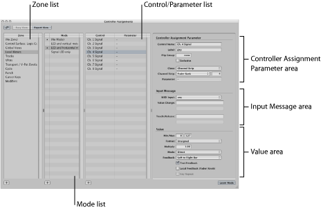
In Expert view, the Controller Assignments window contains the following fields, menus, and buttons that you use to edit assignment parameters and define zones and modes.
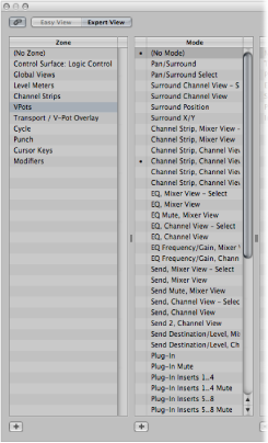
- Zone list: Displays the available zones for the device. The first entry “(No Zone)” is for zoneless assignments—assignments that are always active, regardless of the active zone. Select a zone in the list to see its modes (in the Mode list), and its current assignments (in the Control/Parameter list). You can also double-click a zone to rename it. See Getting to Know Zones and Modes.
- Mode list: Displays the modes for the currently selected zone. The first entry “(No Mode)” is for modeless assignments. Select a mode in the list to see its assignments in the Control/Parameter list, and make it the selected zone’s active mode. You can also double-click a mode to rename it. See Getting to Know Zones and Modes.
- Control/Parameter list: Select the assignment you want to edit. The left column displays the name of the control, and the right column displays the name of the parameter being controlled (in an abbreviated form). The parameters of the selected assignment appear in the fields to the right of the list. See Controller Assignments Window Expert View Settings.
Note: You can select multiple assignments in the list, but only the parameters of the first selected assignment are displayed. When multiple assignments are selected, operations performed via the Edit menu can be applied to all selected assignments. All other operations apply only to the first assignment.
- Controller Assignment Parameter area: All aspects of the selected controller assignment parameter are shown, and can be changed, in this area. See Controller Assignment Parameter Area.
- Input Message area: The port and MIDI input message can be altered directly. Some fields in this section are merely displays, and cannot be changed. See Input Message Area.
- Value area: The range of values, and response, of the controller assignment to incoming messages is determined in this area. Feedback to the display of control surfaces can also be determined here. See Value Area.
Controller Assignments Window Expert View Settings
This section outlines each parameter shown in the fields on the right side of the Controller Assignments window when in Expert view. Detailed descriptions of each parameter can be found in Using the Control Name and Label Fields.
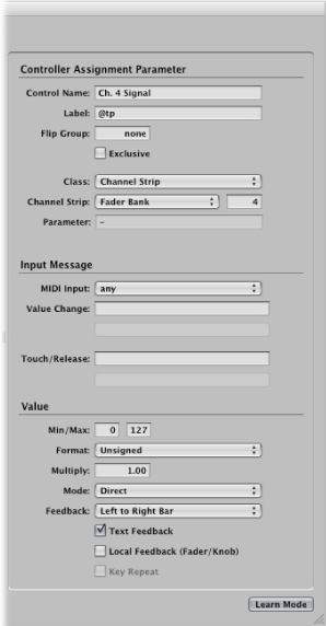
The area at the top right shows the following parameters:
- Control Name field: Displays the name of the controller for supported devices. For unsupported devices, Learned is displayed. See Using the Control Name and Label Fields.
- Label field: Displays characters that represent the label for the assignment on the control surface’s display. You can view this much like a scribble strip on a mixer. See Using the Control Name and Label Fields.
- Flip Group field: Enter an integer to define a flip group for the assignment. See Setting the Flip Group and Exclusive Parameters.
- Class pop-up menu: Choose the class of parameter (parameter type) you want to assign. See Setting Class Pop-Up Menu Parameters.
Note: Depending on the chosen class, different fields and pop-up menus for that class appear below the Class pop-up menu.
- Parameter/Mode pop-up menu and field: Depending on your choice in the Class pop-up menu, you can choose from dozens of different parameters and modes. The options available change as different classes are selected.
- Group/Track/Command/Key field pop-up menu: These options also change depending on your choice in the Class pop-up menu.
- Bank Type pop-up menu: This pop-up menu determines the bank relationship of the assigned parameter. This can be as per the Group setting, By One, or By Bank.
The area at the center right shows the following parameters. See Editing Input Message Parameters in Expert View for details.
- MIDI Input pop-up menu: Choose a MIDI input source (MIDI Port or Caps Lock Keyboard). This can be changed by incoming MIDI messages, shown in the Value Change field.
- Value Change field: Displays incoming MIDI messages that cause a value change.
- Touch/Release field: Enter an integer value to force incoming MIDI messages to change the touch/release status of the selected parameter. This only applies to control surfaces that offer touch-sensitive controls (where touching or releasing a fader, for example, enables or disables reception of data from the control surface).
The area at the bottom right shows the following parameters. See Editing Value Parameters in Expert View for details.
- Min and Max fields: Enter integer values to set the range of incoming MIDI values.
- Format pop-up menu: Choose the format used to encode negative values.
- Multiply field: Enter a value to scale incoming MIDI values.
- Mode pop-up menu: Choose the mode used by incoming values to modify the current parameter value.
- Feedback pop-up menu and checkboxes: Choose the display format of the parameter value (on the control surface display, if applicable).
Assigning and Deleting Controllers in Expert View
You can use the Learn process to assign controllers when the Controller Assignments window is in Expert view, just as you would in Easy view. You can also assign controllers to classes of Logic Pro parameters that are not accessible in Easy view.
Choose Logic Pro > Preferences > Control Surfaces > Controller Assignments (or use Command-K), and click the Expert View button.
Choose a zone or mode (unless you want to make a modeless assignment), and click the plus button in the lower-left corner of the Control/Parameter list.
A new, blank assignment appears in the Control/Parameter list.
Click the Learn Mode button to start the Learn process.
Move the controller (on your control surface) that you want to assign to the selected parameter.
Moving the controller sends a MIDI message to Logic Pro, thus “teaching” Logic Pro which controller you are assigning. The Learn Mode button remains active, allowing you to make further assignments.
The incoming MIDI message appears in the Input message field. Once Logic Pro has received the message, choose the class of parameter you want to assign from the Class pop-up menu.
Assign the parameter by making appropriate choices in the pop-up menus and fields that appear below the Class pop-up menu.
Note: A detailed explanation of classes and other assignment parameters can be found in Using the Control Name and Label Fields.
When you finish, click the Learn Mode button (or press Command-L) to complete the Learn process.
Tip: You can use the shortcut described in Assigning a Series of Controllers in Easy View to assign a series of controllers to a series of similar parameters.
Should you accidentally move the wrong controller in Learn mode, you can easily delete an unwanted assignment.
Select the assignment that you want to delete in the Control/Parameter list.
Choose Edit > Delete (or press the Delete key).
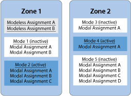
Getting to Know Zones and Modes
You can define a group of controllers as a zone in Expert view, and switch all controls in a zone to different parameters, all in one operation. Using a Mackie Control, for example, you can define the eight rotary encoders as a zone, and switch them between pan, send level, and plug-in parameters. You can also define multiple zones for a control surface: one for the encoders, and a second one that switches the function keys (F1 to F8) to different functions.
Each set of zone parameters is called a mode. A zone can contain one or more modes, but only one mode can be the active mode at any given time. A zone can also contain assignments that are always active, regardless of the active mode. (These are known as modeless assignments.)
The simultaneous use of modal and modeless assignments allows you to do things such as:
Define a zone that switches between two modes (or functions) by pressing and releasing a control surface modifier button (such as Shift or Option) while using a particular function button (on the control surface).
Define a zone that allows you to use modeless assignments for things like updating the display, Transport functions, and Save and Undo operations. The same zone could contain a modal assignment for all Volume and Pan controls. Switching to another mode would provide access to EQ parameters. In both modal situations, the display, Transport, and Save and Undo functions would be available.
A mode can contain any number of assignments. Only the assignments for the active mode are processed by Logic Pro. Assignments of inactive modes are ignored.
You can switch the active mode for a zone by making special assignments. See Defining Zones and Modes.
Zones and modes can be defined across multiple control surfaces, to support the use of control surface groups.
The following example illustrates one possible arrangement of zones and modes, and shows how you can define them, hierarchically:
Defining Zones and Modes
You can only define zones and modes in the Expert view of the Controller Assignments window.
Click the Add button in the lower-left corner of the Zone list.
A new, blank zone appears in the Zone list. It is highlighted, allowing you to immediately rename it.
Enter a name for the zone.
If you want to add controllers to the zone, see Assigning and Deleting Controllers in Expert View.
Click the Add button in the lower-left corner of the Mode list.
A new, blank mode appears in the Mode list. It is highlighted, allowing you to immediately rename it.
Enter a name for the mode.
If you want to add controllers to a mode, see Assigning and Deleting Controllers in Expert View.
Reassigning a Controller in Expert View
The procedure for reassigning an active controller (an assigned controller in the active mode) is different from that of an inactive controller (one with an assignment in an inactive mode).
Use the Learn process described in Assigning and Deleting Controllers in Expert View to assign an active controller (one with an assignment in the active mode), and choose one of the options shown in the dialog:
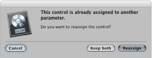
Cancel: Deletes the new assignment, retaining the existing assignment.
Keep Both: Retains the new and old assignments. Used typically when one knob controls multiple parameters as a macro.
Reassign: Deletes all existing active assignments for this parameter. Used to reassign a function key (F1 to F8, for example) to a new key command.
Use the Learn process described in Assigning and Deleting Controllers in Expert View to assign a controller in an inactive mode. Note that the new assignment becomes part of the active mode in the same zone that contained the previous, inactive assignment.
This is typically used as follows: Supported control surfaces generally have empty user pages available, allowing for new encoder assignments. You would select a particular user page mode (page 3, for example), and then learn an assignment for the encoder.
Using the Control Name and Label Fields
The following describes the use and options available for the Control Name and Label fields in the Controller Assignment Parameter area at the top right of the Expert View window.
Shows the name of the control. For supported devices, the control surface name is used. For assignments created with the Learn process on unsupported control surfaces, the control name defaults to Learned. You can enter a new name in the field. The control name is for display only, and has no effect on functionality.
For supported control surfaces, shows characters that represent the label for the assignment that appears on the control surface display. Unsupported control surfaces can only send information, not receive it, and cannot display an assignment label.
If the field contains fixed text, it can contain any number of characters. When used as a placeholder for dynamically created text, however, the field contains three characters that represent the label. The first character is always @, followed by two additional characters.
- Second Character: This character is used to define a type for the event label; for example, track, Insert slot, Send slot, and so on.
- Third Character: This character is used to define a value for the chosen event label type, such as the track number or name.
For example, “Send@s#” translates as “Send1,” “Send2,” and so on.
The following table shows the possible meaning for the second character.
Second character | Meaning |
|---|---|
t | Track |
r | Surround |
s | Send slot |
S | Number of sends |
e | EQ band |
E | Number of EQs |
p | Insert slot |
i | Instrument |
The following table shows the possible meaning for the third character.
Third character | Meaning |
|---|---|
# | Number of above (track number, Send slot, EQ band, Insert slot) |
n | Name of above |
p | Name of parameter addressed by the assignment |
P | Name of first parameter |
o | Parameter offset, counted from 1 |
O | Maximum parameter offset, counted from 1 |
b | Parameter bank (= parameter offset/bank size), counted from 1 |
B | Total number of banks (= parameter offset/bank size), counted from 1 |
Setting the Flip Group and Exclusive Parameters
The following describes the use and options available for the Flip Group field and Exclusive checkbox in the Controller Assignment Parameter area at the top right of the Expert View window.
Enter the same integer value for two assignments, to define a counterpart for Flip mode (for supported control surfaces that offer Flip mode). By setting a fader and an encoder to the same flip group, for example, they are coupled. To set “none,” enter a value of 0.
For unsupported devices, you need to set up two active assignments, both of which use the same flip group. One assignment needs to be absolute (using a fader, for example), the other relative (encoder, for example).
When selected, the assignment deactivates all other assignments that have Exclusive turned off for the same control (on supported control surfaces). This limits the overwriting of a modeless assignment to particular modes. For example, faders normally control volume. To create a mode where faders control the send level, select Exclusive.
Setting Class Pop-Up Menu Parameters
Choose the class of assignment (the type of destination parameter controlled) from the pop-up menu. Different options appear below the Class pop-up menu when you choose a class. The following section describes the different classes, and the options available for each.
Choosing the Mode Change class lets you use an assignment to switch from one mode to another. An additional Mode pop-up menu appears below the Class pop-up menu, allowing you to choose between available modes. For example, the assignment buttons on a Mackie Control can be used to choose different modes for the encoders.
Note: The mode chosen in the Mode pop-up menu is only activated when the Value section: Mode menu is set to Direct.
If any of the other Value section: Mode menu options is chosen, the following applies:
- Toggle: The assignment toggles between the zone’s first mode and the chosen mode. The mode change assignment must be located in the same zone.
- Relative: Useful for stepping up and down through modes in a zone (using two buttons) or for choosing a mode with an encoder. The minimum destination parameter represents this zone’s first mode, and the maximum represents the zone’s last mode. The mode change assignment must be located in the same zone.
- Rotate: Useful for stepping through all available modes with a single button. Used with a Jog Wheel, for example: Off > Scrub > Shuttle > Off. The minimum destination parameter represents this zone’s first mode, and the maximum represents the zone’s last mode. The mode change assignment must be located in the same zone.
Choosing the Global class lets you use an assignment to control global parameters. A Parameter pop-up menu appears below the Class pop-up menu, offering the parameters listed in the following table.
Note: All options listed in the table below only work in relative mode, where changes are relative to the starting value/position, and so on.
Global options | Explanation |
|---|---|
Playhead | This assignment controls the position of the playhead; feedback is sent in the format chosen in the control surface group’s Clock Display parameter. |
Playhead (Beats) | As above, but feedback is sent in beats format. |
Playhead (Time Code) | As above, but feedback is sent in SMPTE time code format. |
Playhead (Beats, Scrubbing) | Moving the controller doesn’t set the playhead position, but initiates scrubbing. The format is defined by the control surface group’s Format parameter. The controller value defines the scrubbing speed. |
Move Locators | Moves left and right locators. |
Left Locator | Sets left locator. |
Right Locator | Sets right locator. |
Move Punch Locators | Moves punch in and punch out locators. |
Punch In Locator | Sets punch in locator. |
Punch Out Locators | Sets punch out locator. |
Marker Position | Edits position of current marker. |
Marker Length | Edits length of current marker. |
Global options | Explanation |
|---|---|
Nudge selected Regions/Events | Nudges the selected regions or events by the chosen nudge value. (See below.) |
Any Solo | Feedback only. On if any (track or region) Solo button is active. |
Nudge Value | Controls the nudge value used for Nudge selected Regions/Events. Switches between tick, division, beat, bar, frame, 1/2 frame. |
Scrub Status | Sets the scrubbing status for the Playhead parameter (beats, scrubbing). Possible values are set clock, audio scrubbing, shuttle. |
Automation of all tracks | Switches the automation status of all tracks between the following values: Off, Read, Touch, Latch, Write. |
Alert Text, Alert Button, Alert Icon | Used by plug-ins to define special Alert mode. This is mainly of use to control surface developers. |
Dummy | Used to temporarily disable a modeless assignment, by using the Exclusive checkbox. See Control Name Field. |
Cycle | Toggles the Cycle function on and off. |
Autopunch | Toggles the Autopunch function on and off. |
Go to Marker | Allows you to move the playhead to a marker number. An additional number field below the Parameter pop-up menu is used to determine the destination marker number. |
Group Clutch | Sets the automation group clutch; automation groups are disabled when the clutch is enabled. For buttons, sets the group clutch to 1 when the button is pressed, and sets it to 0 when the button is released. |
Active Sense | Used by some control surfaces (such as the HUI) to process incoming Active Sensing messages. |
Shuttle Speed | Sets the shuttle (forward and backward) speed directly. Use this for controllers (usually knobs) that send an absolute, rather than relative, value. |
Waveform Zoom | Sets the waveform zoom level in the key focus Arrange area. |
Quantize value | Sets the Quantize value in the key focus window (if this parameter is available). |
Division | Sets the Division value in the key focus window (if this parameter is available). |
Horizontal Zoom | Sets horizontal zoom in the key focus window (if this parameter is available). |
Vertical Zoom | Sets vertical zoom in the key focus window (if this parameter is available). |
Choosing the Channel Strip class lets you use an assignment to set a channel strip parameter. A Channel Strip pop-up menu appears below the Class pop-up menu, offering the following parameters.
Channel strip type | Explanation |
|---|---|
Selected track | Normally corresponds to the selected Arrange track. Exception: If the control surface group’s Track Lock parameter is active, the “selected” track is the one that was chosen when Track Lock was enabled. |
Fader Bank | Addresses a channel strip in the control surface group’s current View mode (Arrange, All, Tracks, Single). This is dependent on the current Fader Bank value for this mode (see below). Example: The View mode is All, the All view Fader Bank is five, and the number next to this parameter is two. Thus, the eighth channel strip in the All view is addressed (Fader Bank and No. are 0-based, so add 1). |
Index | Same as the Fader Bank setting, but doesn’t depend on the current Fader Bank value. |
Audio | An audio channel. The numerical value (No.) determines which audio channel is addressed (again: 0-based; to address audio channel 2, use a value of 1). |
Software Instrument | Same as Audio setting, for software instrument channel strips. |
Bus | Same as Audio setting, for bus channel strips. |
Auxiliary | Same as Audio setting, for auxiliary channel strips. |
Output | Same as Audio setting, but for output channel strips. |
Master | The Master channel strip; if it does not exist in the project, the first output channel strip is addressed. |
If you choose the Fader Bank, Index, Audio, Software Instrument, Bus, Auxiliary, Output, or Master setting in the Channel Strip pop-up menu, the following two parameters become available:
- Number field: A 0-based offset, which is added to the channel strip number. The typical use for this field is for sequential controls: Fader 1 uses offset 0, Fader 2 uses offset 1, and so on.
- Parameter field: Text description of the addressed parameter. Can only be set by choosing the Logic Pro > Preferences > Learn Assignment for [parameter name] menu item. Note that for plug-in and instrument parameters, Parameter Page offsets apply, allowing you to shift the parameter addressing up and down by page.
Choosing the Key class lets you use assignments to emulate keystrokes on your computer keyboard. You can enter the key to emulate in the Key field, which appears below the Class pop-up menu. This is not case-sensitive.
Choosing the Key Command class lets you use an assignment to perform a key command. You can enter the key command in the Command field, which appears below the Class pop-up menu. Some key commands provide on/off or enabled/disabled feedback.
If you want your key command assignment to be executed repeatedly, select the Key Repeat checkbox at the bottom of the Controller Assignments window. For further information, see “Key Repeat Checkbox” in Editing Value Parameters in Expert View.
Click the Show button to open the Key Commands window. The key command shown in the Command field is automatically selected and shown in the Key Commands window.
Choosing the Control Surface Group class allows you to set a property for the control surface group (that the assignment belongs to). When you choose this class, a Parameter pop-up menu appears below the Class pop-up menu. This pop-up menu allows you to choose one of the options described in Control Surface Group Parameters, or one from those listed in the following table.
Note that assignments for unsupported control surfaces always belong to the first control surface group.
Parameter option | Additional info |
|---|---|
Fader Bank for Current View | Maps to the fader bank for the currently used View mode. This way, you need only one assignment per left/right button for all View modes. |
Filter for All View | When this parameter is selected, eight additional checkboxes (for the eight channel strip types) are displayed, when the View mode is All. Depending on the Value mode, these switches define which channel strips are displayed (by using Direct mode) or which are toggled (by using X-OR mode). |
Fader Bank for: MIDI Channel Strips, Input Channel Strips, Audio Channel Strips, Instrument Channel Strips, Aux Channel Strips, Bus Channel Strips, Output Channel Strips | These fader bank parameters are used in All View when only one channel strip type is displayed. This allows you to switch between several channel strip types, while retaining the current fader bank for each type. |
If you choose one of the fader bank or parameter page settings in the Parameter pop-up menu, the following Bank Type options appear below the pop-up menu.
- By One: The fader bank or parameter page is shifted by one channel strip or parameter.
- By Bank: The fader bank or parameter page is shifted by the number of displayed channel strips or parameters.
- CS Group Setting: The fader bank or parameter page is shifted by the value defined for the Parameter Page Shift Mode control surface group parameter.
Choosing the Automation Group class allows you to use the assignment to set an automation group parameter.
When this class is chosen, a Group field appears below the Class pop-up menu. You can determine the edited group by entering a number in the field. Entering a “0” sets this parameter to the group selected for the Automation Group parameter (in the control surface group parameters).
A Parameter pop-up menu also appears below the Group field, allowing you to choose the automation group parameter for the assignment. For further information, see the Group Settings section of the Logic Pro User Manual.
Editing Input Message Parameters in Expert View
The parameters in this section let you control different aspects of MIDI input.
When you choose a MIDI input (port) from the pop-up menu, all assignments that use the same input are changed accordingly. If the assignment belongs to a supported control surface, the device’s MIDI input also changes in the Setup window.
This makes it easy for you to create default assignments for a new control surface. These new assignments can be moved to other computers by copying your com.apple.Logic.cs preferences file. Simply paste this preference file into the Preferences folder of another computer, open the Controller Assignments window in Expert view, and change the MIDI Input parameter of one assignment (as applicable to the MIDI setup on the other computer).
Shows incoming MIDI messages that cause a value change in the destination parameter, and lets you edit these MIDI messages.
The Value Change field displays the message as a sequence of hexadecimal bytes. The plain language meaning appears below the field. The placeholders for the variable part of the message are:
- Lo7: Low 7 bits of the value (LSB or Least Significant Bits)
- Hi7: High 7 bits of the value (MSB or Most Significant Bits)
For messages containing only a Lo7 placeholder, the value is treated as 7 bit. For messages containing both a Lo7 and Hi7 placeholder, the value is treated as 14 bit. The order of Lo7 and Hi7 is honored, and there may be constant bytes in between. This allows you to define Control Change LSB and MSB portions. For example, B0 08 Hi7 B0 28 Lo7 indicates a 14-bit message.
Note: When you enter multiple MIDI messages, always enter each message completely, being sure to repeat the status byte, even if it’s the same. It may help to write out the message to ensure that the correct byte works, as you can’t know what status the previously sent message had.
For messages containing neither Lo7 nor Hi7 placeholders, Logic Pro assumes an incoming value of 1. This is typical for pressed or released buttons. Also see “Multiply Field” in Editing Value Parameters in Expert View.
Enter an integer value to use the incoming MIDI message for status changes of the destination parameter from touched to released, or vice versa. A non-zero value means touched; a value of 0 means released. The messages are shown and edited in the same way as the Value Change field.
Note: The Touch/Release setting only applies to the Channel Strip assignment class, and to parameters that can be automated.
Editing Value Parameters in Expert View
The parameters in this section let you control different aspects of the values for incoming MIDI messages.
Enter an integer value to set the minimum and maximum range for incoming values represented by Lo7 and Hi7. Typically, the minimum defaults to 0, and the maximum defaults to 127. Some control surfaces (such as the CM Labs Motor Mix) may use the same message, with different value ranges, for different controls. For more specific information, refer to the documentation that came with your device.
Choose the encoding format for negative values in the 7-bit portions sent over MIDI. The choices are:
- Unsigned: No negative values are possible. The full 7- or 14-bit range is treated as a positive number. The value range is 0 to 127 (7 bit) or 0 to 16383 (14 bit).
- 2’s complement: If the most significant bit is set, the value is negative. To obtain the absolute value, invert all bits and add 1. The value range is from –128 (7 bit) to 127 or –8192 to 8191 (14 bit).
- 1’s complement: If the most significant bit is set, the value is negative. To set the absolute value, invert all bits. Note that this allows two possible encoding values for zero. The value range is –127 to 127 (7 bit) or –8191 to 8191 (14 bit).
- Sign Magnitude: If the most significant bit is set, the value is negative. To set the absolute value, clear the most significant bit. Note that this allows two possible encoding values for zero. This results in a value range of –127 to 127 (7 bit) or –8191 to 8191 (14 bit).
The appropriate format for a device is usually specified in its documentation. If unavailable, check the control surface manufacturer’s website or contact them for more information.
Enter a scaling value for incoming values. This is especially useful for button presses that have a value of 1. For example:
To set the automation mode to Write, set Multiply to 4.00, and Mode to Direct.
To decrement a parameter by 1 with a button press, set Multiply to –1.00, and Mode to Relative.
Choose the mode used by incoming values to modify the current parameter value. The choices are:
- Direct: The incoming value is used as the parameter value.
- Toggle: If the parameter’s current value is 0, it is set to the incoming value. All other values set the parameter value to 0. This option is useful for buttons that toggle a value: Mute, Solo, and so on.
- Scaled: The incoming value is scaled from its value range to the destination parameter’s value range. This is useful for faders and rotary encoders.
- Relative: The incoming value is added to the parameter’s current value. Used by encoders, but also for buttons that increment/decrement by a certain amount (set by the Multiply parameter).
- Rotate: The incoming value is added to the parameter’s current value, cycling between maximum and minimum values. This is useful for button presses that cycle between modes: automation mode, for example.
- X-OR: The value defines a bit mask (a filter, in other words), which is applied to the parameter’s current value with the “exclusive or” Boolean operation. Useful for enabling/disabling single channel strip types in All view.
For On/Off parameters, Mode is set to Toggle by default. It is set to Scaled for absolute controls (faders and knobs, for example), or to Relative for encoders.
Choose the display format for the parameter’s current value (on the control surface display). The choices are:
- None: No feedback is sent.
- Single Dot/Line: LED rings: only one LED; LCDs: a single vertical line.
- Left to Right Bar: A bar from the minimum to the current value.
- Bar from Center: A bar from the center position to the current value.
- Right to Left Bar: A bar from the current value to the maximum.
- Q/Spread: Two equal bars from the center to the current value.
- Ascending Bar: A bar from the bottom to the current value.
- Descending Bar: A bar from the top to the current value.
- Text Only: LED rings: no feedback; LCDs: no feedback as a graphics element.
- Automatic: Dependent on the currently assigned parameter, the most suitable feedback mode is used: Plug-in and Instrument parameters carry this information, Pan displays a Single Dot/Line, and all other parameters display a bar that runs from left to right (Left to Right Bar).
Note: Feedback only works for supported control surfaces, and not all settings are available for all controls.
When selected, a text representation of the current value is sent to the control surface’s display. The control surface display capabilities determine the display position and number of characters that are used.
When selected, no feedback is sent while the parameter is in Touch mode. This prevents motorized faders from “fighting” against the user.
When selected, the assignment is repeatedly executed. The Key Repeat Rate slider—set in the Mac OS X Keyboard & Mouse preferences—determines how quickly Logic Pro repeats the assignment. The duration that the button/controller must be held for, before the assignment is repeated, is set with the Delay Until Repeat slider in the Keyboard & Mouse preferences.
Key Repeat is particularly useful for the zoom function. For example, if you assign a Key Repeat command to the Mackie Control Zoom buttons, holding down the Zoom In button will continuously zoom in the Logic Pro window until the button is released. This mirrors the behavior of the Zoom key commands. The alternative is to repeatedly press the (Mackie Control) Zoom buttons to zoom in or out more than one level.
Note: The Key Repeat checkbox is only available for key commands, key presses, and relative value changes. If any other assignment class is selected, the checkbox is dimmed.
The default key command assignments support the Key Repeat function (if useful or applicable to the control surface or device), making changes unnecessary for use of this functionality.
If you want to enable the Key Repeat function for your own assignments, you may need to use the re-learn option for the assigned message. Key Repeat messages must include the Lo7 byte, which provides information on the up (released) or down (pressed) state of the assigned button.
Logic Pro guides you through the re-learning process. The current MIDI message is automatically cleared, Learn mode is activated, and a help tag prompts you to send the desired MIDI message.
Releasing the assigned button—after learning the MIDI message—automatically creates the Lo7 byte, and assigns the Lo7 value (for the button release message) to the Min parameter. The Lo7 value for the button pressed message is automatically assigned to the Max parameter.
Typically, the value range of 1 to 127 is used for the button pressed message. The zero (0) value is generally used for the button release message.
Note: Some control surfaces may use different value ranges (CM Labs Motormix, for example). Assigning appropriate Min and Max values ensures that the Key Repeat function will work with such devices. This, however, means that you need to take care when manually changing the Min or Max value for a key command; in cases where the Min and Max values do not match the button pressed (on) and button released (off) states, the complete assignment will not work. Consult your control surface manual for further information about the values it uses.